
 EN
EN
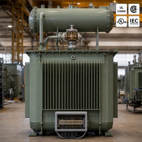
Чилийн уурхайны гүйцэтгэгчид ажилладаг худалдан авах менежер июльд биднийг дуудаж, худалдан авагчдын хүлээж буйгаас илүүтэр дуудлагуудын нэгийг тавьж: «Хэрэв бид 15 МВА-ийн тосонд живсэн трансформатор бидний үйлдвэрийн үйлдвэрлэсэн бүтээдгийг захиалж, түүнд хамгаалалт оршоох уу, эсвэл түүнийг тусдаа худалдан авах уу?» Товч хариулт — хоёул. Саванд суурилж буй төхөөрөмжүүд нэгжтэй хамт хүргэдгийн харин реле-ийн тохируулалт, ЦТ-ийн харьцаа, таслалтын логика — бүтээдгийн худалдан авагчийн хамгаалалт инженертэй хамт шийддэг; мөн биднийг талд гарч буй ихэнх гэмтлийн шалтгаан нь түүн дээрх шилжүүлэлт, бүтээдгийн өөрсдийнх нь биш.
Хамгаалалт нь нэг шалтгаанаар оршин байдаг: дотоод гэмтэл үүсгэдэг энергия, як танк нь түүнийг урт хугацаанд хадгалахын тулд зөвхөн төсөөлж бүтээгдсэн биш. Типичн 7% импеданс үед, терминалд болтой гэмтэл номиналь хүчдлийн арван дөрвөн дахин илүү гүйдэл үүсгэж чаддаг. Танк доторх ороолтын богино холболт нь түүн доторх тосонд энерги хийдэг миллисекундын дотор. Хамгаалалтын схем нь үзэгдэх үйл явдлыг цагт нь — цахилгаан, гидравлик юм уу дулааны аргаар — илрүүлж, танк хагарах юм уу тос төрөхөөс өмнө нэгжийг салгаж өгөх үүрэгтэй.
Тосоор дүүрсэн трансформатор дээр юу хамгаалалт хүртэл хүрдэг
Трансформаторын хамгаалал нүүрлүг тосонд живсэн трансформатор хоёр бүлгийн дотор хуваагддаг. Нөгөө талд, танк дээр суурилж буй төхөөрөмжүүд: гол танк ба хадгалагч хоорондын гуурцаг дээрх Бухгольц хийн реле, танкны дэд хавхын дээрх даралт тайрах төхөөрөмж, тосны температур ба ороолтын температур илтгэгчид (сигнал холбогчтой), тосны түвшин илтгэгч. Хоёрдугаарт, кубикл юм уу дэд станцын панель дээрх гадаад хамгаалах релейд: гүйдлийн хэт ачаалал, ялгавар ба газар-хүртүүр функцүүд, түүн дотроо анхдагч талын салгагчийг салгах.
Тэр хуваалт худалдан авагсадын хувьд чухал. Танк дээрх төхөөрөмжүүд трансформаторын хүрээнд ордог — үйлдвэр түүнд суурилж, холбож, шүүмжилж. Гадаад релэйн хамгаалах схем нь их түүнд төслийн хамгаалах урсгалд тодорхойлогддог, түүний тохируулалт нь үйлчилгээний бүрэлдэхүүн юм уу ЕПС-ийн хамгаалах инженерийн хариуцлагад ордог. Бид хамгийн их тааралддаг зөрчил нь: худалдан авагсад үйлдвэрний хүрээнд релэйн координаци хамрагддаг гэж үздэг, харин хамгаалах инженер трансформаторын хамгаалах панель бүрэн холбогдсон дүрсдэг гэж үздэг. Хоёулан худалдаг, түүн дотроо ажиллуулж үзэх үе шат хоцрогддог.
Бухгольцын реле: Зөвхөн танк дотор тааралдаж буй төхөөрөмж
The Бухгольцын реле энэ нь хэвийн ажиллах үед тосоор дүүрсэн гол танк ба хадгалагч хоорондын гуурцагт байрладаг. Тэр хоёр ялгаатай гэмтлийн шинж тэмдэгт бүлгийг илрүүлдэг. Удаан гэмтлүүд — изоляци үлдэж, холболт сулрах, жижиг хэсэгчлэн цахилгааны төхөөрөмж — тос дотор хий үүсгэдэг, хий дээш хөдөлж релегийн камер дотор цуглуудаг. Хийн дүүрэн хэмжээ нь анхны шатны хязгаарыг хүртэл өсөх үед, хөвөрц унаж, сигнализацийн хавтгайг хаадаг. Хүчтэй гэмтлүүд — жишээ нь ороомгийн хооронд фаз-фазын богино холболт — гуурцаг дотор тосны урсгалыг шүүрүүлдэг. Урсгал барьцааг хөдөлгөж, аварга хавтгайг мөчлөн хаадаг, электрик хэмжилтийн доод талын хариу үйлдлээс илүү хурдан.
Бидний туршилтын талбарт, бүх Бухгольцын реле тавцан дээрх туршилт хийн тавьж суурьлуулахын өмнө хийн туршилт хийдэг. Бид агаарыг тосны орц дээрс нь даралт үүсгэж, хоолойн хэмжээд харгалзахаар тогтоосон газын хэмжээнд сүүдлүүр идэвхжихийг шалгаж, дараа нь цахилгааныг түргэн үйлдэлд оруулж, хүчдлийн хавтгай дээрх холболтын хүрээ бүтнэлж, утасны холболт маршаллинг хайрцагт хүрж буйг баталж. Холболтын утасны зураг авч, ФАТ-ийн баримтад бүртгүүлдэг, учир нь холын талбарт бүртгүүлсэн холболтын алдаа техникчдийн хүртэлх замын хугацаа бүтнэлж, холболтын шүүлт хийх үүрэгт үүрэгт үүрэгт үүрэгт үүрэгт үүрэгт үүрэгт үүрэгт үүрэгт үүрэгт үүрэгт үүрэгт үүрэгт үүрэгт үүрэгт үүрэгт үүрэгт үүрэгт үүрэгт үүрэгт үүрэгт үүрэгт үүрэгт үүрэгт үүрэгт үүрэгт үүрэгт үүрэгт үүрэгт үүрэгт үүрэгт үүрэгт үүрэгт үүрэгт үүрэгт үүрэгт үүрэгт үүрэгт үүрэгт үүрэгт үүрэгт үүрэгт үүрэгт үүрэгт үүрэгт үүрэгт үүрэгт үүрэгт үүрэгт үүрэгт үүрэгт үүрэгт үүрэгт үүрэгт үүрэгт үүрэгт үүрэгт үүрэгт үүрэгт үүрэгт үүрэгт үүрэгт үүрэгт үүрэгт үүрэгт үүрэгт үүрэгт үүрэгт үүрэгт үүрэгт үүрэгт үүрэгт үүрэгт үүрэгт үүрэгт үүрэгт үүрэгт үүрэгт үүрэгт үүрэгт үүрэгт үүрэгт үүрэгт үүрэгт үүрэгт үүрэгт үүрэгт үүрэгт үүрэгт үүрэгт үүрэгт үүрэгт үүрэгт үүрэгт үүрэгт үүрэгт үүрэгт үүрэгт үүрэгт үүрэгт үүрэгт үүрэгт үүрэгт үүрэгт үүрэгт үүрэгт үүрэгт үүрэгт үүрэгт үүрэгт үүрэгт үүрэгт үүрэгт үүрэгт үүрэгт үүрэгт үүрэгт үүрэгт үүрэгт үүрэгт үүрэгт үүрэгт үүрэгт үүрэгт үүрэгт үүрэгт үүрэгт үүрэгт үүрэгт үүрэгт үүрэгт үүрэгт үүрэгт үүрэгт үүрэгт үүрэгт үүрэгт үүрэгт үүрэгт үүрэгт үүрэгт үүрэгт үүрэгт үүрэгт үүрэгт үүрэгт үүрэгт үүрэгт үүрэгт үүрэгт үүрэгт үүрэгт үүрэгт үүрэгт үүрэгт үүрэгт үүрэгт үүрэгт үүрэгт үүрэгт үүрэгт үүрэгт үүрэгт үүрэгт үүрэгт үүрэгт үүрэгт үүрэгт үүрэгт үүрэгт үүрэгт үүрэгт үүрэгт үүрэгт үүрэгт үүрэгт үүрэгт үүрэгт үүрэгт үүрэгт үүрэгт үүрэгт үүрэгт үүрэгт үүрэгт үүрэгт үүрэгт үүрэгт үүрэгт үүрэгт үүрэгт үүрэгт үүрэгт үүрэгт үүрэгт үүрэгт үүрэгт үүрэгт үүрэгт үүрэгт үүрэгт үүрэгт үүрэгт үүрэгт үүрэгт үүрэгт үүрэгт үүрэгт үүрэгт үүрэгт үүрэгт үүрэгт үүрэгт үүрэгт үүрэгт үүрэгт үүрэгт үүрэгт үүрэгт үүрэгт үүрэгт үүрэгт үүрэгт үүрэгт үүрэгт үүрэгт үүрэгт үүрэгт үүрэгт үүрэгт үүрэгт үүрэгт үүрэгт үүрэгт үүрэгт үүрэгт үүрэгт үүрэгт үүрэгт үүрэгт үүрэгт үүрэгт үүрэгт үүрэгт үүрэгт үүрэгт үүрэгт үүрэгт үүрэгт үүрэгт үүрэгт үүрэгт үүрэгт үүрэгт үүрэгт үүрэгт үүрэгт үүрэгт үүрэгт үүрэгт үүрэгт үүрэгт үүрэгт үүрэгт үүрэгт үүрэгт үүрэгт үүрэгт үүрэгт үүрэгт үүрэгт үүрэгт үүрэгт үүрэгт үүрэгт үүрэгт үүрэгт үүрэгт үүрэгт үүрэгт үүрэгт үүрэгт үүрэгт үүрэгт үүрэгт үүрэгт үүрэгт үүрэгт үүрэгт үүрэгт үүрэгт үүрэгт үүрэгт үүрэгт үүрэгт үүрэгт үүрэгт үүрэгт үүрэгт үүрэгт үүрэгт үүрэгт үүрэгт үүрэгт үүрэгт үүрэгт үүрэгт үүрэгт үүрэгт үүрэгт үүрэгт үүрэгт үүрэгт үүрэгт үүрэгт үүрэгт үүрэгт үүрэгт үүрэгт үүрэгт үүрэгт үүрэгт үүрэгт үүрэгт үүрэгт үүрэгт үүрэгт үүрэгт үүрэгт үүрэгт үүрэгт үүрэгт үүрэгт үүрэгт үүрэгт үүрэгт үүрэгт үүрэгт үүрэгт үүрэгт үүрэгт үүрэгт үүрэгт үүрэгт үүрэгт үүрэгт үүрэгт үүрэгт үүрэгт үүрэгт үүрэгт үүрэгт үүрэгт үүрэгт үүрэгт үүрэгт үүрэгт үүрэгт үүрэгт үүрэгт үүрэгт үүрэгт үүрэгт үүрэгт үүрэгт үүрэгт үүрэгт үүрэгт үүрэгт үүрэгт үүрэгт үүрэгт үүрэгт үүрэгт үүрэгт үүрэгт үүрэгт үүрэгт үүрэгт үүрэгт үүрэгт үүрэгт үүрэгт үүрэгт үүрэгт үүрэгт үүрэгт үүрэгт үүрэгт үүрэгт үүрэгт үүрэгт үүрэгт үүрэгт үүрэгт үүрэгт үүрэгт үүрэгт үүрэгт үүрэгт үүрэгт үүрэгт үүрэгт үүрэгт үүрэгт үүрэгт үүрэгт үүрэгт үүрэгт үүрэгт үүрэгт үүрэгт үүрэгт үүрэгт үүрэгт үүрэгт үүрэгт үүрэгт үүрэгт үүрэгт үүрэгт үүрэгт үүрэгт үүрэгт үүрэгт үүрэгт үүрэгт үүрэгт үүрэгт үүрэгт үүрэгт үүрэгт үүрэгт үүрэгт үүрэгт үүрэгт үүрэгт үүрэгт үүрэгт үүрэгт үүрэгт үүрэгт үүрэгт үүрэгт үүрэгт үүрэгт үүрэгт үүрэгт үүрэгт үүрэгт үүрэгт үүрэгт үүрэгт үүрэгт үүрэгт үүрэгт үүрэгт үүрэгт үүрэгт үүрэгт үүрэгт үүрэгт үүрэгт үүрэгт үүрэгт үүрэгт үүрэгт үүрэгт үүрэгт үүрэгт үүрэгт үүрэгт үүрэгт үүрэгт үүрэгт үүрэгт үүрэгт үүрэгт үүрэгт үүрэгт үүрэгт үүрэгт үүрэгт үүрэгт үүрэгт үүрэгт үүрэгт үүрэгт үүрэгт үүрэгт үүрэгт үүрэгт үүрэгт үүрэгт үүрэгт үүрэгт үүрэгт үүрэгт үүрэгт үүрэгт үүрэгт үүрэгт үүрэгт үүрэгт үүрэгт үүрэгт үүрэгт үүрэгт үүрэгт үүрэгт үүрэгт үүрэгт үүрэгт үүрэгт үүрэгт үүрэгт үүрэгт үүрэгт үүрэгт үүрэгт үүрэгт үүрэгт үүрэгт үүрэгт үүрэгт үүрэгт үүрэгт үүрэгт үүрэгт үүрэгт үүрэгт үүрэгт үүрэгт үүрэгт үүрэгт үүрэгт үүрэгт үүрэгт үүрэгт үүрэгт үүрэгт үүрэгт үүрэгт үүрэгт үүрэгт үүрэгт үүрэгт үүрэгт үүрэгт үүрэгт үүрэгт үүрэгт үүрэгт үүрэгт үүрэгт үүрэгт үүрэгт үүрэгт үүрэгт үүрэгт үүрэгт үүрэгт үүрэгт үүрэгт үүрэгт үүрэгт үүрэгт үүрэгт үүрэгт үүрэгт үүрэгт үүрэгт үүрэгт үүрэгт үүрэгт үүрэгт үүрэгт үүрэгт үүрэгт үүрэгт үүрэгт үүрэгт үүрэгт үүрэгт үүрэгт үүрэгт үүрэгт үүрэгт үүрэгт үүрэгт үүрэгт үүрэгт үүрэгт үүрэгт үүрэгт үүрэгт үүрэгт үүрэгт үүрэгт үүрэгт үүрэгт үүрэгт үүрэгт үүрэгт үүрэгт үүрэгт үүрэгт үүрэгт үүрэгт үүрэгт үүрэгт үүрэгт үүрэгт үүрэгт үүрэгт үүрэгт үүрэгт үүрэгт үүрэгт үүрэгт үүрэгт үүрэгт үүрэгт үүрэгт үүрэгт үүрэгт үүрэгт үүрэгт үүрэгт үүрэгт үүрэгт үүрэгт үүрэгт үүрэгт үүрэгт үүрэгт үүрэгт үүрэгт үүрэгт үүрэгт үүрэгт үүрэгт үүрэгт үүрэгт үүрэгт үүрэгт үүрэгт үүрэгт үүрэгт үүрэгт үүрэгт үүрэгт үүрэгт үүрэгт үүрэгт үүрэгт үүрэгт үүрэгт үүрэгт үүрэгт үүрэгт үүрэгт үүрэгт үүрэгт үүрэгт үүрэгт үүрэгт үүрэгт үүрэгт үүрэгт үүрэгт үүрэгт үүрэгт үүрэгт үүрэгт үүрэгт үүрэгт үүрэгт үүрэгт үүрэгт үүрэгт үүрэгт үүрэгт үүрэгт үүрэгт үүрэгт үүрэгт үүрэгт үүрэгт үүрэгт үүрэгт үүрэгт үүрэгт үүрэгт үүрэгт үүрэгт үүрэгт үүрэгт үүрэгт үүрэгт үүрэгт үүрэгт үүрэгт үүрэгт үүрэгт үүрэгт үүрэгт үүрэгт үүрэгт үүрэгт үүрэгт үүрэгт үүрэгт үүрэгт үүрэгт үүрэгт үүрэгт үүрэгт үүрэгт үүрэгт үүрэгт үүрэгт үүрэгт үүрэгт үүрэгт үүрэгт үүрэгт үүрэгт үүрэгт үүрэгт үүрэгт үүрэгт үүрэгт үүрэгт үүрэгт үүрэгт үүрэгт үүрэгт үүрэгт үүрэгт үүрэгт үүрэгт үүрэгт үүрэгт үүрэгт үүрэгт үүрэгт үүрэгт үүрэгт үүрэгт үүрэгт үүрэгт үүрэгт үүрэгт үүрэгт үүрэгт үүрэгт үүрэгт үүрэгт үүрэгт үүрэгт үүрэгт үүрэгт үүрэгт үүрэгт үүрэгт үүрэгт үүрэгт үүрэгт үүрэгт үүрэгт үүрэгт үүрэгт үүрэгт үүрэгт үүрэгт үүрэгт үүрэгт үүрэгт үүрэгт үүрэгт үүрэгт үүрэгт үүрэгт үүрэгт үүрэгт үүрэгт үүрэгт үүрэгт үүрэгт үүрэгт үүрэгт үүрэгт үүрэгт үүрэгт үүрэгт үүрэгт үүрэгт үүрэгт үүрэгт үүрэгт үүрэгт үүрэгт үүрэгт үүрэгт үүрэгт үүрэгт үүрэгт үүрэгт үүрэгт үүрэгт үүрэгт үүрэгт үүрэгт үүрэгт үүрэгт үүрэгт үүрэгт үүрэгт үүрэгт үүрэгт үүрэгт үүрэгт үүрэгт үүрэгт үүрэгт үүрэгт үүрэгт үүрэгт үүрэгт үүрэгт үүрэгт үүрэгт үүрэгт үүрэгт үүрэгт үүрэгт үүрэгт үүрэгт үүрэгт үүрэгт үүрэгт үүрэгт үүрэгт үүрэгт үүрэгт үүрэгт үүрэгт үүрэгт үүрэгт үүрэгт үүрэгт үүрэгт үүрэгт үүрэгт үүрэгт үүрэгт үүрэгт үүрэгт үүрэгт үүрэгт үүрэгт үүрэгт үүрэгт үүрэгт үүрэгт үүрэгт үүрэгт үүрэгт үүрэгт үүрэгт үүрэгт үүрэгт үүрэгт үүрэгт үүрэгт үүрэгт үүрэгт үүрэгт үүрэгт үүрэгт үүрэгт үүрэгт үүрэгт үүрэгт үүрэгт үүрэгт үүрэгт үүрэгт үүрэгт үүрэгт үүрэгт үүрэгт үүрэгт үүрэгт үүрэгт үүрэгт үүрэгт үүрэгт үүрэгт үүрэгт үүрэгт үүрэгт үүрэгт үүрэгт үүрэгт үүрэгт үүрэгт үүрэгт үүрэгт үүрэгт үүрэгт үүрэгт үүрэгт үүрэгт үүрэгт үүрэгт үүрэгт үүрэгт үүрэгт үүрэгт үүрэгт үүрэгт үүрэгт үүрэгт үүрэгт үүрэгт үүрэгт үүрэгт үүрэгт үүрэгт үүрэгт үүрэгт үүрэгт үүрэгт үүрэгт үүрэгт үүрэгт үүрэгт үүрэгт үүрэгт үүрэгт үүрэгт үүрэгт үүрэгт үүрэгт үүрэгт үүрэгт үүрэгт үүрэгт үүрэгт үүрэгт үүрэгт үүрэгт үүрэгт үүрэгт үүрэгт үүрэгт үүрэгт үүрэгт үүрэгт үүрэгт үүрэгт үүрэгт үүрэгт үүрэгт үүрэгт үүрэгт үүрэгт үүрэгт үүрэгт үүрэгт үүрэгт үүрэгт үүрэгт үүрэгт үүрэгт үүрэгт үүрэгт үүрэгт үүрэгт үүрэгт үүрэгт үүрэгт үүрэгт 0.5 хоног.
Суулгах дэлгэрэнгүй мэдээлэл нь хийн релеүдийн нэр хүртэл хүрдэг. Релэ нь тавиур дээр түүний сум консерваторын зүүн тал руу зааж байхаар тавигдаж, нормаль ажиллах үед тос түүн дагуу урсдаг, хий мөн түүн дагуу дамжидаг. Бид нэг удаа объектод ирж, фланц-шайбат гуммитын хооронд харагдах агаарын сав бүтээж, релэ суулгаж, гэмтлийн үүсгүй цуглуулж хуримтлагдаж буй хийн улмаас долоо хоногт дуудлага үүсгэж буй үзүүлэлтийг харж бид. Тосны түүвэр авах цэг болон релэний шалгах вентиль — эд нарын байршлыг нь нэгж бүтээх үед олох нь зүйтэй, учир нь түүдүүр ажиллаж буй нэг жилийн дотор хэрэглэдэг.
Дараалан үүсгүй ба ялгаварын хамгаалал: Төхөөрөмжийн дугаарууд юу газар?
Гадаад релэ хамгаалал ANSI/IEEE төхөөрөмжийн дугааруудаар хүүрдэг, та тархалтын ангилалд хийгүүр дугаарууд 50, 51 ба 87T-г удаан хүртэл хүрдэг. 50моментан дараалан үүсгүй: гэмтлийн гүнзгий токс хүртэл ачаалалын токсоос их хурдан түүнд хариу үзүүрлүүр. 51хугацаа хоцрогдсон гүйдлийн хамгаалалт: түүний тусламжтайгаар доод талын төхөөрөмжүүдтэй зохицуулж, хоолойн гэмтэл хоолойд цэвэрлэгддэг, трансформаторд биш. 87T трансформаторын дифференциал хамгаалалт: түүн дээр трансформаторын анхдагч ороомгийн орж ирж буй гүйдлийг хоёр талд суурилж буй гүйдлийн хувиргагчид (CT) ашиглан хэмжсэн хоёрдогч ороомгийн гарч буй гүйдлтэй харьцуулж, хоёрын утгууд таарахгүй бол трансформаторын саванд бүүрхүүлд үүсгүүр гэмтлийг хамгийн хурдан, найдвартай аргаар илрүүлдэг.
The Чадлын трансформаторыг хамгаалах IEEE-н заавар (IEEE C37.91-2021) нь 5 МВА-с дээш чадалт, 10 кВ-с дээш хүчдэд ажиллах гурван фазын трансформаторуудын хамгаалалтын хүрээг тодорхойлж, түүнд дифференциал хамгаалалт орж буй бүтэн хамгаалалтын схемийг санал болгож буй. Түүнээс доош чадалт трансформаторуудын хувьд ихэвчлэн хайлах хамгаалалт юм уу зохицуулж буй гүйдлийн хамгаалалт релеүүд ашиглаж буй, түүн дээр дифференциал хамгаалалт бага тохиодог, харин 15 МВА-с дээш чадалт чадлын трансформаторуудын хувьд дифференциал хамгаалалт шаардлагатай. Хэрэв таны хамгаалалтын инженер түүн дээр дифференциал хамгаалалт шаардаж буйгүй бол, яагаад гэдгийг асууж үзэх нь зүйтэй. Заавар нь нийтэд нээлттэй түлхүүр материал бөлүүр бөлүүр, дараагийн RFQ-д өмнө унших нь зүйтэй.
Тохируулалтын философи нь өөртөө тусгай салбар бөлөг, гэтэдүүр нэг тоо — трансформаторын оролт хүчдэлд хамт үүсч буй гүйдэл — худалдан авагчдын хүртэмүүрт бүх цагт байх ёстой. Трансформаторыг тосонд живсэн трансформатор хүчдэлд хамт холбож үүрдэлд оруулах үед магнетик гүйдэл нь хүчдэлд хамт холбож үүрдэлд оруулах үед номиналь гүйдлийн 8–12 дахин их болж, хэдэн цикл дараа бүрхүүрт унаж ирдэг. Хэрвээ мөчлөгийн доторх гүйдлийн хамгаалалтын элемент нь түүнээс доош тохируулж үүрдэлд оруулах үед трансформаторын ажиллагаа зогсож, түүнийг үүрдэлд оруулах үед бүх цагт таслаж ирдэг. Түүн дагуу 50-р хамгаалалтын элемент нь оролт хүчдэлд хамт үүсч буй гүйдлийн хүртэмүүрт дээш тохируулж эсвэл холбож үүрдэлд оруулах үед түрхүүрт хаалтанд бүрхүүрт унаж ирдэг; 51-р хамгаалалтын элемент нь доод талын хоолойн хамгаалалттай координацид орж ирдэг; дифференциал реле нь гармоник хүчдэлд хамт үүсч буй гүйдлийн хүртэмүүрт бүрхүүрт унаж ирдэг — түүн дагуу оролт хүчдэлд хамт үүсч буй гүйдлийг хаяж, гэтэдүүр үнэнхүү дотоод гэмтлийг харж ирдэг. Таны нийлүүлэгч түүнүүдийн тохируулалтыг сонгохгүй; таны хамгаалалтын инженер сонгох ёстой. Трансформаторын үйлдвэрт та хүртэмүүрт тохируулалтын судалгаа хийх болойд шаардлагатай туршилтын өгүлзүүр — импеданс, сүүдрийн муруй, ачаалалгүй алдагдал — хүргүүлэх ёстой.
Дарлалын тайлбар, температур ба тосны түвшин: Схемын үлдсэн хэсгүүд
Гурван нэмэлт танк-дүүрсэн төхөөрөмж та нарын техникийн шаардлагад тодорхой заалт хүртэл оруулж үзэх үүрэгтэй. Даралт холбогч төхөөрөмж нь дотоод даралт газрын холбогч төхөөрөмжийн хариу үйлдлийн хурднаас хурдан өсвөл танкыг хөнгөлөх үүрэгтэй — та үүнийг схемийн механик аюулгүй бүрхүүл вентиль гэж ойлгож болой. Тосны температур индикатор ба ороолтын температур индикатор нь харийн ба аварга холбогч контактуудыг агуулж, ихэвчлэн дундаж ороолтын температурын өсөлт 65 K-т харгалзах тосны дээд температурт тохируулж үзэх үүрэгтэй. Тосны түвшин хэмжигч нь газрын холбогч төхөөрөмжийн хараа хүртэл хүрэхгүй удаан урсгалыг илрүүлж, хадгалах савын тос бүтнэд хоосондорох нь ихэвчлэн хамгаалалт үзэгдэлд хүрэхийн өмнө техник засварын асуудал бөлгөө.
Нэг RFQ цэг үүр: холбоо барих хүмүүсийн жагсаалтыг асуу. Төхөөрөмж бүрд хичнээн хүртэл нөөц тревога ба зогсоох холболтууд байх ёстойг тодорхойл. Холболтууд панелийн тогтмол гүйдэл дээрх удаах хүчдлийн шаардлаж (24, 48, 110 эсвэл 220 В ТГ — ердийн утга), мөн маршаллах хайрцагт терминал хавтас, дулааны бүрхүүл ба гланц хавтас багтаж буйг тодорхойл. Төхөөрөмжид холболтуудыг хүргэлт дараа суулгах нь илүү үнэтэй. Түүнийг RFQ-д нэг мөрөнд тодорхойлох л хэрэг.
Үйлдвэрлэлийн туршилтаар хамгаалах үйл ажиллагааг баталсан
Хамгаалалт нь түүний ард байгаа утасны хэмжээнд л сайн байдаг. Тиймээс бид хоёр удаа шалгаж байна. Эхлээд цахилгаан шалгалтыг хийх хэрэгтэй. IEEE C57.12.00 : харьцаа, хоолой байдал, хучилттай эсэргүүцэл, ачаалалгүй байдал, ачаалал алдсан байдал, импиденц, диэлектрик туршилтууд. Дараа нь стандарт дадлага шалгалтын жагсаалтад хэзээ ч байхгүй хамгаалалтын шалгалтууд: CT-ийн хоолой, харьцааны баталгаажуулалт, болгоны ялгаруулалтын холбооноос эхлэн тоног төхөөрөмжийн хайрцаг хүртэл үргэлжлэх байдал, болон анхны угаах туршилтыг хийхэд цахи
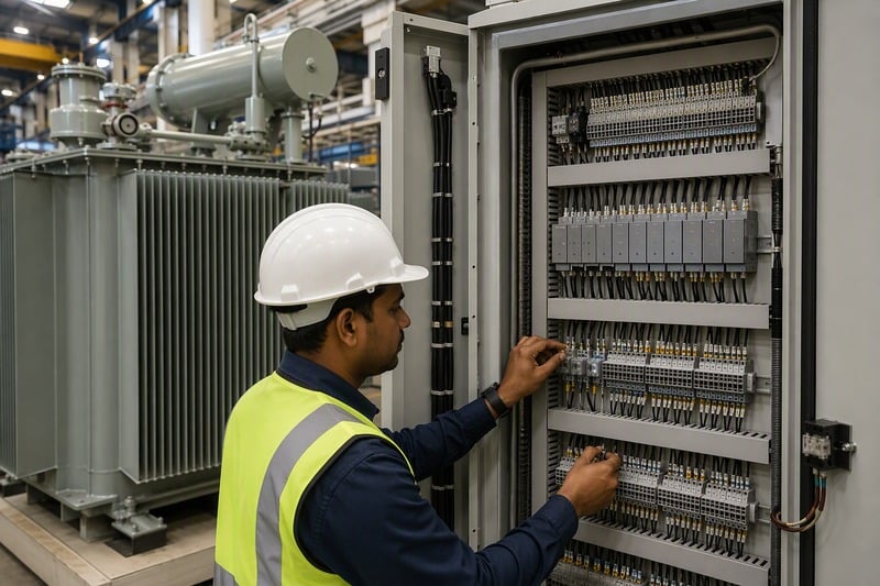
Өнгөрсөн жил нэг үйлчлүүлэгчийн гуравдагч талын шинжигч 20 МВА-ийн нэгжийн анхдагч хуримтлуурт шинжилгээг харахыг хүсжээ. Тест нь маршаллинг хайрцагт нэг КТ-ийн хоёрдогч холболтын поляртет хөндлөн бүүрхийлснийг илрүүлжээ. Үйлдвэрт илрүүлснээр засварлахад хоёр цаг шаардлагатай болжээ. Харин объект дээр илрүүлснээр анхдагч ачаалал өгснөөр дифференциал хамгаалалт алдаатай ажиллах бөөрмөд бөөрмөд — мөн хүн бүр хүсэхгүй хүлээлттүүлэлтийн ярилцлага үүсгэх бөөрмөд бөөрмөд. Түүн дагуу ФАТ-ийн хамгаалалт хэсгийн шинжилгээнд туршилтын тайлан дахь алдагдалд харуулж буй тоон үзүүлэлтүүдтүүн адил анхаарайн төвд бүүрхийлснийг шаардлагатай.
Одоо тоон реле-үүд нь өмнөх цагт электромеханик нэгжүүдийн хана шаардаж байсан ажлыг гүйцэтгэнэ, мөн олон төсөлд реле-үүдийн өгөгдлийг сухой хавтгай (dry contact) газарханы оронд Modbus эсвэл IEC 61850 протоколын дагуу авдаг. Та сонгосон протокол ямар бүүр, үйлдвэрт үлдмүүр асуулт ижил үлдмүүр: хамгаалалтын гурван холболт (CT-ийн төвхөнүүдээс хүчдэл таслах хөдөлгүүр хүртэл) бүтнээр нь туршигдаж уу? Релегүйд зөвхөн тохируулалт зөв хийгдсэн бүүр, CT-ийн хоёрдогч хэлхээ нь нээлттэй бүүр, хүчдэл таслах хөдөлгүүрт холбогдож буй утас бүүр буруу төвхөнүүдтэй холбогдсон бүүр — түүн дагуу үйлдвэрт бүтнээр нь туршигдах нь газарт туршигдах нь харьцангуй хүндрүүлж, зардал нь 10 дахин бага.
Таңын RFQ-д оруулах зургаан асуулт
- Хамгаалалтын ямар төхөөрөмжүүд үйлдвэрт суурилуулж, холбож, ямар нь чөлөөт хаягдмүүр?
- Бухгольц релегүйд: бренд ба загвар; тревога ба хүчдэл таслах стадиудыг туршигдаж уу, FAT файлд зураг хавсаргаж уу?
- CT-үүд: харьцаа, нарийн тодорхойлолтын ангилал (жишээ нь 5P20 хамгаалалтын ангилал), полярностьн диаграмм зурагт оруулж уу?
- Температур, тосны түвшин ба даралт төхөөрөмжүүд SCADA холболтод хөрш хүчдэл таслах хөдөлгүүрт холбогдож буй нэмэлт хавтгай (spare contacts) агуулж уу?
- Үйлдвэрийн туршилтын тайланд CT-ийн анхдагч хийлт ба хавьтлын тасралтгүй байдлын туршилт орж буй, эсвэл зөвхөн үндсэн цахилгааны туршилт орж буй?
- Нэгжтэй хамт ямар хамгаалалтын баримт бичиг илгээдэг — схемын зураг, релеийн заавар, туршилтын гэрчилгээ?
Энэ нь практикт яагаад чухал бөлшүү. Бидний Дунднийн Дорнодод ажилладаг утилити худалдан авагч субстанцын бүх захиалгыг нэг релеийн платформ дээр, нэг хавьтлын техникийн шаардлагууд дээр нийлүүлдэг. Бидний талаас нийлүүлэлт нь бүх нэгжүүдийн хувьд ижил холбогч хуваарь, ижил туршилтын арга зүй, ижил солих хэсгүүдийн жагсаалт гэсэн утгыг илтгэдэг, үүнээс FAT бүтээлт хугацаа бүтээлт хугацаа товчирдог, мөн түүний суурилуулалтын бүрэлдэхүүнд хүртэлх хүртэмж тодорхой болдог.
Райан Электрик 2007 оноос хойш 120 000 м² талбайд тархалт ба хүчдэлийн трансформаторуудыг бүтээж иржээ, мөн 2023 онд Итон компани союзлан ажиллах гэрээ байгуулж, бидний компонентуудын нийлүүлэлт ба FAT дисциплин нь дэлхийн утилитиудын хүлээж иржээ. Дээрх үйлдлүүдийг 37 патент ба UL, CSA, IEEE, DEKRA, CNAS сертификатууд баталгаажуулж — түүн дунд нь таны хамгаалах инженерийн тохиргоо зам замд ордоггүй, бүхнээс түүний ажил хөнгөвтөр болой.
Та утилити, уурхай, үйлдвэрлэлийн төсөлд тосонд живсэн трансформатор тохируулж буй бол, асуулт хүлээн авахдаа ачааллын өгөгдлүүд, системийн хүчдэл ба хамгаалах философи-гүйдлүүдийг биднэд илгээж. Бидний инженерүүд та худалдан авах захиалга өгөхөөс өмнө хамгаалах хүрээ, туршилтын программ ба баримт багц-гүйдлүүдийг баталгаажуулж. Бидний холбооны хуудсаас ашиглаж эсвэл шууд санал хүсэлт илгээж, бид та нарын хүсэлтүүдэд брошюр бус, хариулт илгээмүү.
Зохиогчийн тухай энэ заавар нь 2007 онд бүүрдсэн, Хятадад сууриндаа бүрдсэн трансформаторын үйлдвэрлэгч Ryan Electric-ийн инженерийн болон экспорт хүрээлэнд бүрдсэн бүлгийн гишүүдийн хүчинд бүтээгджээ. Бүлгийн гишүүд Север Америк, Дөрвөлжин Азийн умард хэсэг, Дунднийн аймаг, Африкад үйлчилж буй үйлдвэрлэл, EPC, ашиглалтын худалдан авагчдын хүрээлэнд ашиглалтын инженерийн дэмжлэг, сертификатын дэмжлэг, үйлдвэрлэлийн туршилтын баримт бичиг үүрдүүлж буй.
Агуулгын хүснэгт
- Тосоор дүүрсэн трансформатор дээр юу хамгаалалт хүртэл хүрдэг
- Бухгольцын реле: Зөвхөн танк дотор тааралдаж буй төхөөрөмж
- Дараалан үүсгүй ба ялгаварын хамгаалал: Төхөөрөмжийн дугаарууд юу газар?
- Дарлалын тайлбар, температур ба тосны түвшин: Схемын үлдсэн хэсгүүд
- Үйлдвэрлэлийн туршилтаар хамгаалах үйл ажиллагааг баталсан
- Таңын RFQ-д оруулах зургаан асуулт