Pad Mounted Transformer Installation: Site Requirements and Safety Checklist
A 2,500 kVA pad mounted transformer works hard. It runs year-round through Texas heat, Canadian winters, and everything in between. But two things — and really only two things — determine whether it delivers 20 years of trouble-free operation: how it’s built, and how it’s installed.
The manufacturing side is our job at Ryan. The installation side? That’s where a clear set of requirements, applied before the concrete is poured, makes the difference between a one-day energization and a two-week punch list with the utility inspector.
Site Selection: Where Your Pad Mounted Transformer Lives
Site selection isn’t just about finding a flat spot near the service entrance. It’s about drainage, access, and — perhaps most overlooked — what happens around the transformer five years from now.
Drainage and Elevation
A pad mounted transformer installation must sit above the 100-year flood plain elevation for the site. That’s not a suggestion — it’s in most utility interconnection agreements and referenced by IEEE C57.12.28 for pad mounted enclosure integrity. Even outside flood zones, standing water around the base accelerates corrosion and creates a shock hazard.
The pad surface should slope away from the transformer on all sides with a minimum 2% grade. In our experience with Gulf Coast projects, where seasonal rains are intense, we recommend raising the pad 6 to 12 inches above surrounding grade and adding a gravel perimeter 24 inches wide. This keeps vegetation back, improves drainage, and makes the site look maintained — which matters when a utility inspector walks up.
Vegetation and Clear Zone
Keep a minimum 10-foot clear zone around the transformer free of trees, shrubs, and combustible materials. Not just for fire safety — branches falling on a live-front compartment during a storm is a real outage cause. Underground, tree roots can crack a concrete pad over time. We’ve seen it. The fix is digging up half the site.
Access for Service and Replacement
The transformer will need to be accessed for maintenance, and eventually, replaced. A 3,000 kVA unit weighs roughly 12,000 to 15,000 pounds. Your site needs a driveway or compacted access path capable of supporting a flatbed truck and crane. Minimum recommended width: 12 feet, with no overhead obstructions below 15 feet. The last thing you want is to crane a unit over a finished building because the access road was an afterthought.
Foundation Pad: The Concrete Base That Holds Everything
This section determines whether your transformer stays level for two decades or starts tilting in year three.
Concrete Specification
The transformer foundation pad should be reinforced concrete, minimum 4,000 PSI compressive strength at 28 days. Thickness: no less than 6 inches for units up to 500 kVA, and 8 to 10 inches for larger units above 1,000 kVA. Reinforcement should be #4 rebar on 12-inch centers, both directions, with a minimum 3-inch concrete cover from the bottom.
Here’s a detail most spec sheets miss: the pad should extend at least 6 inches beyond the transformer enclosure footprint on all sides. This prevents edge spalling when heavy tools or equipment rest near the enclosure during maintenance. A chamfered edge (1-inch bevel) also helps — sharp concrete corners chip easily.
Anchor Points and Conduit Stubs
The transformer is bolted to the foundation through its base frame. Bolt locations must match the manufacturer’s drawing exactly — not approximately. A half-inch offset in anchor bolt placement can mean cutting and re-welding base plates on site, which no utility inspector will accept without an engineer’s sign-off.
Conduit stubs for primary and secondary cables should be cast into the pad or sleeved through with PVC. Stub-ups should terminate 2 to 3 inches above the pad surface and be capped during concrete pouring to prevent debris entry. Mark the conduit schedule on the pad surface with a sharpie before the concrete sets — it saves an hour of head-scratching during cable pulling.
Clearance and Access: What NEC and Utility Codes Demand
Working clearances for pad mounted transformer installation are governed primarily by NEC Article 110.26 in the United States and CSA C22.1 in Canada. These are not manufacturer recommendations — they are legal requirements that a utility or AHJ inspector will verify.
Minimum Working Space
|
Condition |
Minimum Clearance |
|
Front of enclosure (door side, live parts exposed, ≤ 150V to ground) |
3 feet (914 mm) |
|
Front of enclosure (door side, 151–600V to ground) |
3.5 feet (1.07 m) |
|
Front of enclosure (601V–15kV, with grounded parts on opposite side) |
4 feet (1.22 m) |
|
Sides and rear (no live parts accessible) |
Typically 3 feet, verify with manufacturer |
|
Overhead clearance above working space |
6.5 feet (1.98 m) minimum |
Door Swing and Bollard Protection
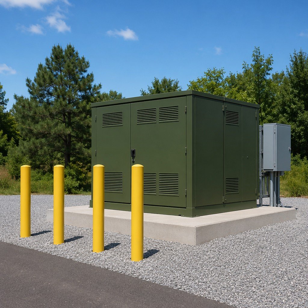
This one trips up a lot of first-time installers: the enclosure doors must be able to open a full 90 degrees without obstruction. If the transformer sits in a parking lot or near vehicle traffic, install steel bollards filled with concrete, minimum 4-inch diameter, set 3 feet deep, rising 3 to 4 feet above grade. Place them 3 to 4 feet from the enclosure face — close enough to stop a vehicle, far enough to allow door swing.
Ventilation Clearance
Pad mounted enclosures rely on natural air circulation through louvers. Maintain at least 6 inches of clearance behind the enclosure for air intake and exhaust. Do not back the transformer directly against a wall or fence. If a noise barrier wall is required, use an open design with at least 50% free area and maintain 12 inches minimum standoff.
Grounding and Bonding: The One Step Nobody Should Skip
If there’s one thing that separates a safe pad mounted transformer site from a liability, it’s the grounding system. A proper ground grid doesn’t just protect people — it ensures protective devices operate correctly during a fault.
Ground Resistance Target
The goal: 5.0 Ohms or less ground resistance, measured using the fall-of-potential method (IEEE 81). In rocky or sandy soils where hitting 5 Ohms is difficult, the National Electrical Code (NEC 250.53) allows up to 25 Ohms for a single rod, but most utility interconnection standards require a supplementary electrode beyond that. A ground ring — #2/0 bare copper buried 18 to 24 inches deep in a loop around the pad, bonded to the transformer ground pad at two points — is the most reliable approach.
What Gets Bonded
Transformer enclosure (ground pad on the enclosure frame). Secondary neutral (bonded to the ground bus inside the LV compartment). Conduit and armored cable entering the transformer (bond both ends). Foundation rebar (ufer ground — rebar cage tied with tie wire, stubbed up to the ground pad). Fence or bollard posts (each post gets its own ground connection back to the ring).
The Neutral-Ground Bond
In a separately derived system (which a pad mounted transformer almost always is), the neutral-to-ground bond must be made at exactly one point: the transformer’s ground bus or the first downstream disconnect. A second bond anywhere else on the system creates parallel neutral current paths — a violation of NEC 250.6 and a source of nuisance GFCI trips. Mark the bonding jumper location clearly inside the enclosure so the next technician doesn’t add a second one by mistake.
Pre-Energization Checklist: 8 Things to Verify Before You Flip the Switch
After the pad is poured, the transformer is set, cables are terminated, and grounding is complete — but before the first call to the utility — verify these eight items:
|
# |
Check Item |
What to Look For |
|
1 |
Visual inspection |
No shipping damage, doors open/close fully, gaskets intact |
|
2 |
Pad level |
Within 0.25 inch across the pad surface in all directions |
|
3 |
Anchor bolts |
All torqued to manufacturer spec; no missing nuts or washers |
|
4 |
Ground resistance |
Measured ≤ 5.0 Ohms; test report on file |
|
5 |
Cable terminations |
Torque marks on all lugs; no exposed conductor; proper bending radius |
|
6 |
Phase rotation |
Verified with phase rotation meter; matches site requirements |
|
7 |
Oil level / pressure |
For oil-filled units: oil level correct; pressure/vacuum gauge within range |
|
8 |
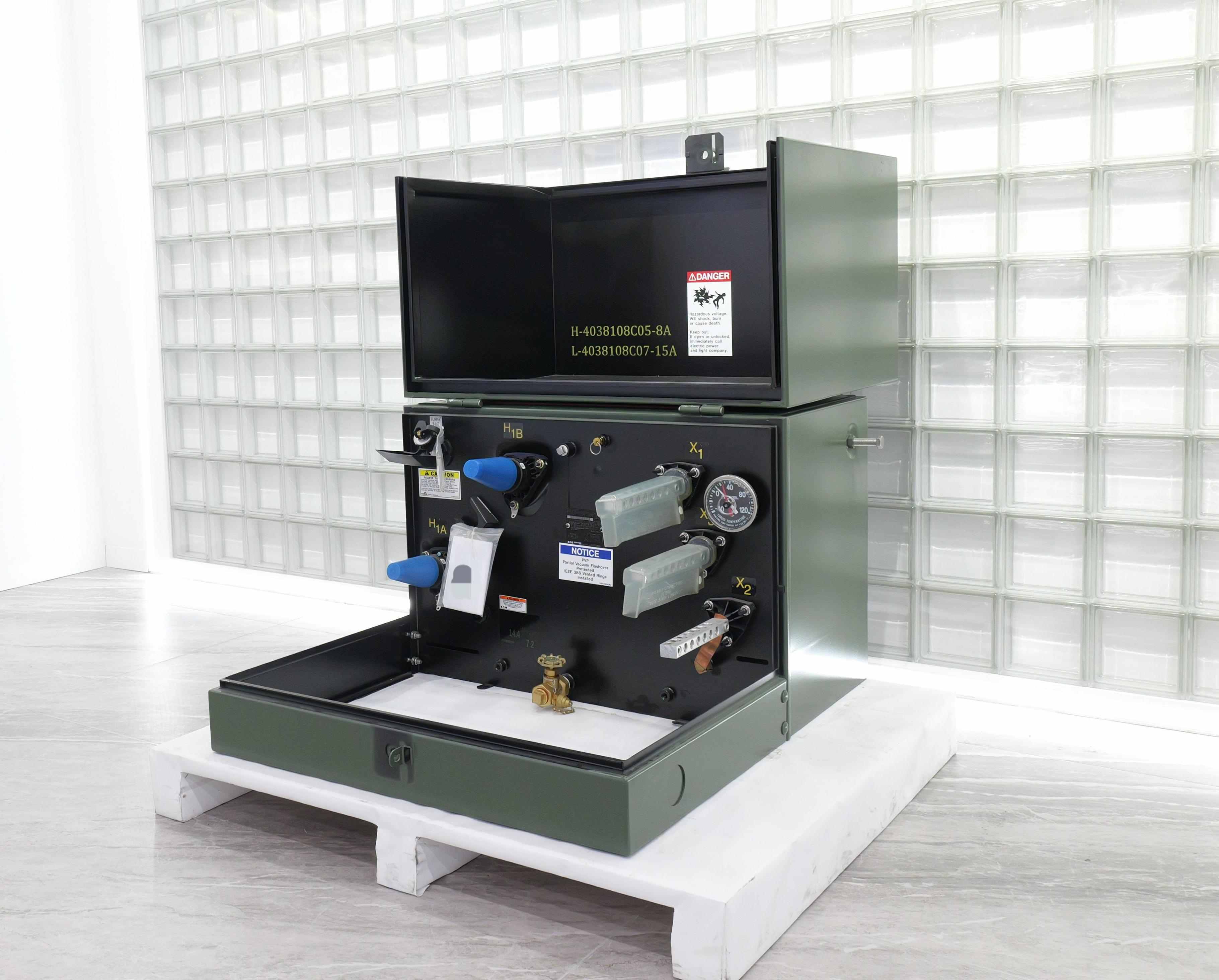
Nameplate verification |
kVA, voltage ratio, impedance match the project specification exactly |
Run these eight checks, document them with photos, and keep the record in the transformer file. When the utility inspector arrives, they’ll see a prepared site — and that sets the tone for the whole energization.
What a Smooth Installation Looks Like — Lessons from the Field
After shipping pad mounted transformers to North American projects for years, our service team has seen both the one-day successes and the two-week headaches. Here’s what the smooth ones have in common:
Build the foundation early. The single biggest source of project delay is the transformer arriving on site before the pad is ready. Concrete needs 28 days to reach design strength. Back-schedule from your energization date — not your delivery date — and pour the pad at least four weeks in advance.
Use the manufacturer’s drawing, not a generic template. Every transformer model has specific anchor bolt patterns, conduit entry locations, and door swing requirements. A generic civil drawing that worked for Brand A won’t necessarily work for Brand B. We provide foundation layout drawings with every unit — hand them to your civil contractor before they order rebar.
Schedule utility inspection early. Don’t wait until all eight checklist items are done to call the utility. At the pad-pour stage, invite the inspector for a pre-pour check of rebar placement and conduit stubs. At the cable termination stage, request a pre-energization walkthrough. Two short visits beat one long one where they find three things wrong and you lose a week.
The Eaton standard matters. As an Eaton joint venture partner, Ryan’s manufacturing quality management system follows a process that Eaton has audited and approved. When a utility inspector sees documentation that connects to a recognized supply chain, questions get answered faster. It’s not about the badge — it’s about the traceability.
Ready to Start Your Installation?
A well-executed pad mounted transformer installation starts before the concrete truck arrives. Get the pad right, get the clearances right, get the grounding right — and the rest falls into place.
We ship pad mounted transformers with a complete installation package: foundation layout drawings, torque specifications, grounding design guidelines, and the pre-energization checklist. If your project is in the planning phase, our engineering team can review your site layout and flag potential issues before they become change orders.
Need a pad mounted transformer with full installation support? Contact our engineering team for a technical proposal →

 EN
EN