
 EN
EN
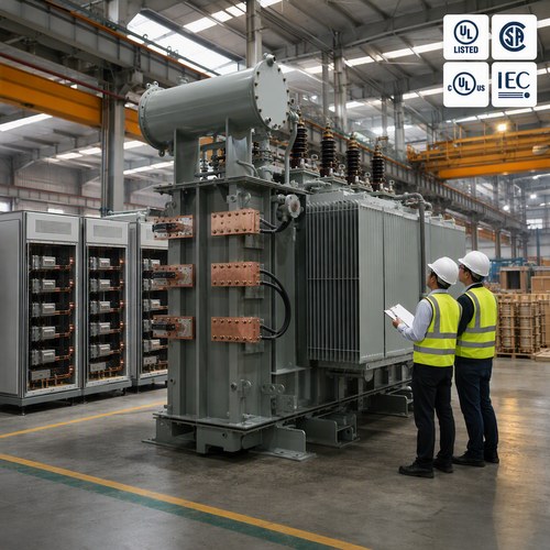
Last spring, a plating facility in Monterrey sent us an RFQ for a '500 kVA rectifier transformer' and nothing else. Two weeks later their utility engineer was on the phone: the 6-pulse rectifier on their new line was pushing current total harmonic distortion past 30% at the point of common coupling, and the penalty clause in their power contract had already started ticking. The transformer was not the problem. The specification was.
What a Rectifier Transformer Does That a Standard Unit Cannot
A rectifier transformer feeds a DC load — electrolysis cells, plating baths, DC drives, traction substations, furnace supplies — through a diode or thyristor bridge. That sounds simple, but it changes the design rules completely.
A standard distribution transformer is engineered for a sinusoidal, steady load. A rectifier transformer must handle high secondary current at low voltage, non-sinusoidal current waveforms, and duty cycles that often run 24 hours a day. In electrolysis, a single line can draw tens of thousands of amps at a few hundred volts DC. The secondary winding current density, the busbar connections, and the tank shielding all have to be designed around that reality, not around a typical 480V feeder.
Here is the part most buyers miss. The nameplate kVA of a rectifier transformer is only part of the story. The real design drivers are the DC voltage and current of the process, the pulse number of the rectifier, and the harmonics the load injects back into the AC network. Change any one of them and you are specifying a different transformer.
Why the 12-Pulse Design Changed the Game
Harmonics are the reason 12-pulse rectifier transformer configurations exist. A 6-pulse rectifier generates characteristic harmonics of order 6k±1 — the 5th and 7th being the largest — and input current total harmonic distortion (THD) typically lands between 25% and 35% at full load. On a weak network, that level of harmonic distortion triggers capacitor bank failures, neutral overcurrents, and utility penalties.
A 12-pulse arrangement uses two 6-pulse bridges fed from a transformer with two secondaries shifted 30 electrical degrees apart — one delta-connected, one wye-connected. The 5th and 7th harmonic currents cancel at the transformer terminals, the dominant remaining harmonics are the 11th and 13th, and current THD drops to roughly 10–15%. For the deepest reductions, 24-pulse designs with a 15° shift push THD into single digits.
The trade-offs are real, and they are documented. A 2021 study published by MDPI compared conventional 12-pulse transformer units against autotransformer versions and showed how the magnetic design choice changes size, losses, and filtering requirements — worth reading before you lock a topology. An older but still-cited IEEE paper does the same comparison for 12- and 24-pulse rectifier transformers in traction substations. Both papers make the same point: the pulse number is a system decision, not an accessory.
The Specs That Actually Matter
When you write the next RFQ, build the technical data table around these parameters:
| Parameter | What to specify | Why it matters |
| Rated power (kVA/MVA) | Calculate from DC volts × DC amps ÷ efficiency, not from AC habit | DC loads have power factor and form factor far from 1.0 |
| Secondary voltage / current | Nominal DC volts and amps of the process | Drives winding current density and busbar design |
| Impedance | Typically 5–8% | Limits short-circuit current; too low stresses the rectifier |
| Temperature rise | 65 K top-oil for oil-immersed units | DC-heavy load profiles increase stray losses |
| Winding & insulation | Copper vs aluminum, insulation class | Life expectancy under continuous overload |
| Tap changer | No-load or on-load (OLTC) | Electrolysis cells need tight DC voltage regulation |
| Harmonic requirement | Target THD or K-factor per IEEE 519 | Defines whether you need 6-, 12-, or 24-pulse |
One number worth remembering: for an oil-immersed electrolysis transformer running a continuous DC duty, a 65 K top-oil temperature rise at full load leaves almost no thermal margin for harmonics. If the process drives the unit past 80% of nameplate for long periods, ask for the stray-loss calculation in the design report. Most failures we see in the field trace back to unspecified harmonics, not to kVA.
Where Buyers Get It Wrong
After fifteen years of quoting these units, the mistakes repeat themselves:
- Specifying from the AC nameplate. A 1,000 kVA distribution habit gets applied to a DC process that needs 1,400 kVA of transformer capability once harmonics and form factor are counted.
- Ignoring the utility's THD limit. The PCC requirement determines the pulse number. If the grid code says 5% voltage THD and you buy 6-pulse, the problem is solved at your cost, not the utility's.
- Forgetting the cable and busbar length. Long DC runs between the transformer and the rectifier add inductance and voltage drop that no transformer can fix.
- Treating the test report as paperwork. The temperature-rise test with the actual load profile, not just the guaranteed values, is the only document that proves the unit can survive your duty.
Here is a real example from our shop. A client in Southeast Asia running an electrolysis line originally ordered a 6-pulse unit at 45 kA DC. During the design review we flagged the THD projection, and the order changed to a 12-pulse rectifier transformer with a 30° phase-shifted secondary pair. The utility acceptance test passed on the first attempt. The premium for the 12-pulse arrangement was paid back in avoided penalties before the first maintenance cycle.
What a Serious Manufacturer Should Provide
A rectifier transformer is a custom product. A serious supplier should be able to hand you, without being asked three times: the design calculation report, the temperature-rise test record with your load profile, the partial discharge test data, the harmonic study input data, and the certification files — UL, CSA, or IEC as your market requires.
At Ryan Electric, we build oil immersed transformer units up to 200 MVA and dry type units in our 120,000 m² factory, with 37 patents behind the winding and shielding designs. As an Eaton joint venture partner since 2023, we have direct access to Eaton component and protection engineering, and our test lab runs temperature-rise, partial discharge, and short-circuit verification before anything ships. For North American projects, UL and CSA listed options are available; for electrolysis and DC drive applications, we routinely supply 12- and 24-pulse configurations with documented stray-loss data.
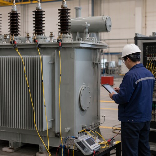
Send Us Your DC Load Profile
The fastest way to get a correct quote is to send the DC load profile, not the transformer nameplate you think you need: nominal DC voltage and current, the duty cycle (hours per day, load factor), the rectifier pulse number or harmonic target, the ambient temperature, and the grid code your site must meet. Whether the project is an electrolysis transformer for a smelter or a compact rectifier unit for a plating line, that information is enough for our engineers to come back with a winding design, a temperature-rise projection, and a realistic schedule.
Send the parameters through ryan-transformers.com and we will respond with a technical proposal within five working days — including the questions you forgot to ask.
About the Author: This article was written by the engineering team at Ryan Electric, an Eaton joint venture partner and UL/CSA-certified transformer manufacturer in Jiangsu, China, serving electrolysis, plating, traction, and DC drive projects across North America, Latin America, Southeast Asia, and the Middle East.