
 EN
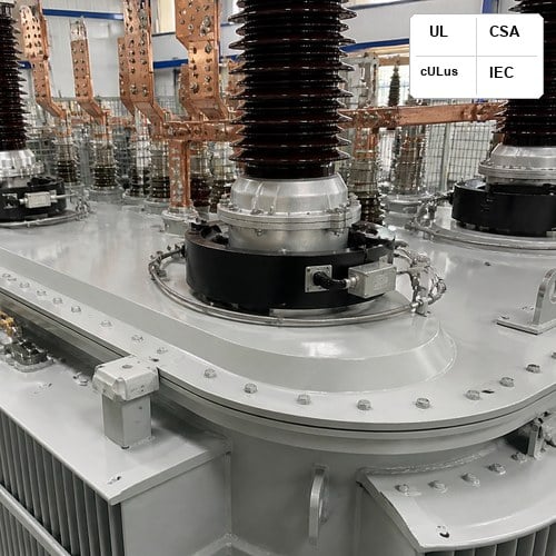
When a medium-voltage or high-voltage substation transformer suffers an external through-fault or internal winding breakdown, the primary defense barrier is not the steel tank or dielectric fluid—it is the protective relaying network. Inside this protection architecture, the transformer bushing current transformer (BCT) operates as the critical sensing transducer. Mounted directly around the grounded lower shank of the high-voltage and low-voltage bushing turrets, the BCT steps down thousands of amperes of primary fault current into a proportional 5 A or 1 A secondary signal that modern digital numerical relays can evaluate.
Yet, across utility substations and industrial renewable plants, protection engineers repeatedly encounter misoperations: differential protection tripping on external inrush, overcurrent relays failing to clear downstream bus faults in time, or core saturation distorting secondary waveforms. Sizing a transformer bushing current transformer requires far more than picking a standard nominal ratio. It demands a rigorous evaluation of BCT accuracy class, secondary winding resistance, connected circuit burden, and the physical limits of CT saturation knee point voltage under severe asymmetrical DC offsets.
Why Bushing Current Transformers Dominate Power Transformer Protection
Unlike standalone free-standing optical or post-type current transformers that require separate foundation pads and structural steel supports, a transformer bushing current transformer is integrated directly into the transformer tank architecture. Built as a toroidal ring core with evenly distributed secondary windings, the BCT slips over the insulated ground sleeve of the condenser bushing or porcelain turret. This physical arrangement provides significant economic and technical advantages: zero additional yard footprint, integrated dielectric insulation provided by the bushing structure itself, and negligible primary leakage inductance.
In substation transformer design, BCTs are typically stacked in sets of two to five per phase. These dedicated secondary cores feed discrete protection and monitoring functions, separating revenue metering, primary differential protection 87T, backup overcurrent (50/51), restricted earth fault (REF 64), and winding temperature indicator (WTI) thermal imaging. However, because toroidal BCTs rely on the transformer bushing conductor as a single-turn primary (1 primary turn), achieving high secondary excitation voltage requires a substantial magnetic core cross-section and hundreds of secondary copper turns.
IEEE C57.13 vs IEC 61869-2 Accuracy Classes: Demystifying the Ratings
Specifying the correct BCT accuracy class begins with navigating the two dominant global standards: IEEE and IEC. North American specifications strictly reference the IEEE C57.13-2016 Standard Requirements for Instrument Transformers, while international and IEC-aligned utility markets mandate compliance with the IEC 61869-2:2012 Current Transformers Specification. Understanding the mathematical differences between these rating systems is essential during substation engineering.
Under IEEE C57.13, relaying accuracy is designated by a letter followed by a secondary terminal voltage rating, such as C100, C200, C400, or C800. The letter "C" indicates that the ratio error can be calculated from excitation curves because leakage flux in fully distributed toroidal cores is negligible. The numerical voltage value (e.g., C800) defines the secondary terminal voltage that the CT can deliver at 20 times nominal secondary current (100 A for a 5 A secondary) into a standard burden without exceeding a 10% ratio correction error.
In contrast, IEC 61869-2 designates protection cores using classes like 5P20, 10P20, or specialized transient classes (TPX, TPY, TPZ). A "5P20" rating indicates a composite error of less than 5% at 20 times the rated symmetrical primary current when loaded with rated burden in volt-amperes (VA).
| Standard & Class | Primary Application | Accuracy / Error Limit | Key Sizing Parameter |
|---|---|---|---|
| IEEE C57.13 Class C (C200/C400/C800) | North American Substation Relay Protection | Max 10% ratio error at 20x nominal current | Secondary terminal voltage at 100 A |
| IEEE C57.13 Class T (T100/T200) | Wound primary / Non-distributed cores | Max 10% ratio error (test verified) | Significant leakage flux must be tested |
| IEC 61869-2 Class 5P / 10P (e.g., 5P20) | International Differential & Overcurrent | 5% / 10% composite error at accuracy limit | Rated VA burden & Accuracy Limit Factor (ALF) |
| IEC 61869-2 Class PR / PX | High-speed Unit Protection / Bus & Gen | Defined knee-point voltage & remanence limit | Knee-point voltage (Vk) and internal resistance |
Core Saturation, Knee-Point Voltage, and Asymmetrical DC Offsets
The most severe hazard in protective relaying is iron core saturation. When a massive short circuit occurs close to the transformer terminals, the primary current is not a clean symmetrical sine wave; it contains an exponential DC decaying component governed by the system X/R ratio. This DC offset drives the magnetic core flux to peak levels up to (1 + X/R) times the steady-state AC flux.
Once core flux density surpasses the saturation knee point of the electrical steel laminations (typically 1.6 to 1.8 Tesla in high-grade grain-oriented silicon steel), the magnetizing impedance collapses. The secondary output current flattens and drops toward zero during each half-cycle. The CT saturation knee point voltage is formally defined under IEEE as the point on the excitation curve where a 45-degree tangent line touches the log-log curve (or a 10% increase in secondary voltage requires a 50% increase in magnetizing excitation current under IEC).
To ensure that high-speed numerical relays execute correct trip decisions without delayed operation or false restraint, the secondary saturation voltage (Vs) must satisfy the classic transient sizing equation:
Vs ≥ I_fault_sec × (1 + X/R) × (R_ct + R_lead + R_relay) (Equation 1)
Consider a practical utility engineering scenario: A 69 kV / 13.8 kV, 20 MVA substation transformer connected to a medium-voltage network with an available symmetrical fault current of 20,000 A and a system X/R ratio of 15. On a 1200:5 multi-ratio tap (ratio = 240), the secondary fault current is 83.33 A. If the secondary BCT winding internal resistance (R_ct) is 0.45 ohms, the 400-foot control cable run (#10 AWG copper, two-way loop) contributes 0.40 ohms, and the digital relay input impedance is 0.05 ohms, the total connected burden is 0.90 ohms.
Under steady-state conditions, the required voltage is 83.33 A × 0.90 ohms = 75.0 V. However, when the asymmetrical DC offset factor (1 + 15 = 16) is factored in for high-speed differential protection 87T clearing, the required instantaneous voltage capability surges to 75.0 V × 16 = 1,200 V. If a project engineer had selected a standard C400 BCT on that 1200:5 tap, the core would saturate within 3 to 5 milliseconds of fault inception, potentially causing differential relay misoperation or failure to trip during an internal phase-to-ground fault.
Multi-Ratio Taps and the Derating Trap in Secondary Sizing
Multi-ratio (MR) transformer bushing current transformer units—such as standard IEEE 600:5, 1200:5, 2000:5, or 3000:5 MR configurations—feature five secondary terminals (designated X1 through X5). By selecting different terminal pairs, commissioning engineers can configure 5 discrete ratios (e.g., 300:5, 400:5, 500:5, 800:5, 900:5, 1000:5, and 1200:5).
Here is the critical design trap that field teams frequently miss: The IEEE accuracy rating (e.g., C800) applies ONLY to the full winding ratio (X1 to X5). When a tap lower than the full winding is utilized, the effective voltage rating decreases in direct linear proportion to the turn ratio! For example, if a C800 1200:5 BCT is tapped down to 600:5 (X2 to X4 or X1 to X3, utilizing only half the secondary turns), the effective secondary terminal voltage rating drops to exactly C400 (400 V).
Furthermore, the internal secondary winding resistance does not decrease proportionally with turns because the inner and outer turn lengths differ across toroidal layers. Sizing calculations must always evaluate the actual connected tap ratio and its corresponding derated excitation curve rather than assuming the full-tap nameplate C-rating.
Best Practices for Transformer Differential Protection (87T) and REF (64)
High-speed unit protection schemes impose the strictest demands on BCT accuracy class matching. In modern percentage-restrained differential schemes (ANSI 87T), current transformers from both the primary and secondary sides of the power transformer are compared. If the high-voltage BCT and low-voltage BCT exhibit different saturation speeds or knee-point voltages during an external out-of-zone short circuit, the resulting spurious secondary error current appears as false differential current, causing an unprovoked transformer trip.
To safeguard system integrity, engineers must enforce three core installation rules:
1. Match Knee-Point Voltages and Characteristics: Select CT ratios such that normal full-load secondary currents are closely matched (between 3.5 A and 4.8 A for 5 A systems), and verify that both primary and secondary BCTs maintain adequate margin above the maximum through-fault saturation voltage.
2. Dedicate Separate Cores for High-Impedance REF Protection: Restricted earth fault (REF 64) protection requires dedicated class C or class PX cores that are completely separate from overcurrent or metering circuits to avoid circulating stray currents through shared neutral leads.
3. Account for Physical Turret and Terminal Box Constraints: Physical space inside transformer bushing turrets is finite. High-accuracy C800 cores require thicker magnetic steel stacks and larger outer diameters. Transformer mechanical designers must coordinate turret height, internal oil circulation channels, and multi-conductor shielding to prevent capacitive noise coupling onto low-level secondary leads.
Ryan Electric Engineering and Testing Standards
At Ryan Electric (瑞安电气), our 120,000 square meter manufacturing base in China integrates advanced automated toroidal winding and precision insulation processing equipment. Across our 180+ advanced production and testing bays, every transformer bushing current transformer undergoes comprehensive factory acceptance testing in full accordance with IEEE C57.13, IEC 61869-2, and UL/CSA certification standards.
When our testing bay engineers mount multi-ratio BCTs inside the high-voltage bushing turrets of a 20 MVA 69 kV substation transformer, the very first field check before securing the top cover is verifying the secondary excitation knee-point voltage against the nameplate curve and confirming that the full tap wiring matches the protective relay schedule without reversed polarity marks. Since 2023, as an official joint venture partner with Eaton, Ryan Electric combines world-class North American engineering standards with agile customized manufacturing, delivering power transformers and pad-mounted substations to utilities, major data centers, and renewable energy developers across the United States, Canada, the Middle East, and Southeast Asia.
Every BCT installed in Ryan Electric transformers is accompanied by computerized test reports detailing ratio error, phase displacement, winding DC resistance, and full excitation curves from 10 V up to saturation, ensuring seamless commissioning with modern Schweitzer (SEL), GE Multilin, Siemens SIPROTEC, or ABB relays.
Procurement Checklist for Specifying Transformer BCTs
Before submitting your transformer specification or Request for Quotation (RFQ), ensure your single-line diagram and data sheets include these seven indispensable parameters:
• Nominal and Maximum Primary Current: Specify maximum continuous loading, emergency overloading (per IEEE C57.91 / IEC 60076-7), and maximum through-fault MVA.
• Required IEEE / IEC Accuracy Class: Specify C400, C800, 5P20, or PX class explicitly for each individual core, indicating target tap ratios.
• Secondary Output Rating: Designate 5 A or 1 A secondary current based on control cable distance to the substation control house.
• Continuous Thermal Current Rating Factor (TRF): Request TRF 1.5 or 2.0 at 30°C ambient if the transformer is designed for future fan cooling (ONAF/OFAF) expansion.
• Terminal Wiring and Shorting Blocks: Require all secondary taps to be pre-wired to heavy-duty sliding shorting terminal blocks inside the external weatherproof transformer control cabinet.
• Polarity Verification: Mandate subtractive polarity with clear H1/X1 stamping aligned toward the transformer exterior.
• Certified Factory Test Curves: Request individual core excitation curves and winding resistance data for relay coordination modeling.
Conclusion and Technical Consultation
Properly sizing your transformer bushing current transformer ensures that your protective relays operate with surgical precision during severe electrical faults while remaining completely secure against nuisance trips during external disturbances. Balancing BCT accuracy class selection, secondary burden impedance, and CT saturation knee point voltage is fundamental to long-term substation reliability.
Whether you are engineering a 115 kV utility substation, a 34.5 kV solar collector substation, or an industrial medium-voltage pad-mounted distribution lineup, Ryan Electric provides custom-engineered transformer solutions tailored to your exact protection and metering specifications. Contact our engineering team today to review your transformer single-line diagrams, calculate BCT sizing parameters, or request a fast, competitive quotation.
About the Author
Senior Substation Protection & Transformer Application Engineering Team at Ryan Electric
With over 18 years of specialized engineering experience in high-voltage power transformer design, substation protection coordination, and North American utility compliance, Ryan Electric’s technical team delivers turnkey transformer engineering solutions across the globe. Our products hold full UL, CSA, IEEE, and DEKRA certifications.
Table of Contents
- Why Bushing Current Transformers Dominate Power Transformer Protection
- IEEE C57.13 vs IEC 61869-2 Accuracy Classes: Demystifying the Ratings
- Core Saturation, Knee-Point Voltage, and Asymmetrical DC Offsets
- Multi-Ratio Taps and the Derating Trap in Secondary Sizing
- Best Practices for Transformer Differential Protection (87T) and REF (64)
- Ryan Electric Engineering and Testing Standards
- Procurement Checklist for Specifying Transformer BCTs
- Conclusion and Technical Consultation
- About the Author