
 EN
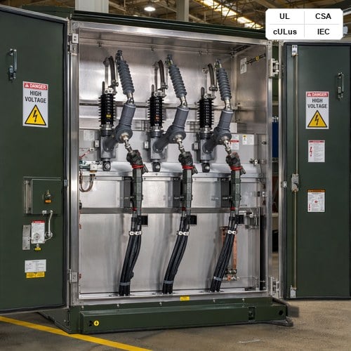
When lightning strikes an overhead distribution line or a vacuum circuit breaker chops inductive magnetizing current during an open-close cycle, the resulting high-frequency voltage transient travels toward the transformer terminal at near the speed of light. Without a properly coordinated surge arrester for transformer installations, this steep-front traveling wave enters the high-voltage winding, creating severe inter-turn dielectric stress that punctures winding insulation, degrades dielectric oil, and leads to catastrophic tank rupture. As a leading pad mounted transformer manufacturer, Jiangsu Ryan Electric Co., Ltd. frequently evaluates substation designs and renewable collector systems where transformers suffered premature dielectric breakdown despite having surge arresters installed on nearby utility poles. In almost every case, the root cause was not equipment defect, but improper arrester selection, excessive lead length inductance, or mismatched Maximum Continuous Operating Voltage (MCOV) ratings.
Specifying the right surge protection requires a thorough understanding of system grounding topologies, Temporary Overvoltage (TOV) withstand curves, discharge current classes, and Basic Impulse Insulation Level (BIL) coordination. Whether engineering a three phase transformer custom build for a utility substation, an offshore wind platform, or a commercial microgrid, selecting and placing the right surge arresters is the ultimate safeguard for reliable power distribution. This guide provides a comprehensive, field-tested engineering framework for sizing MCOV, calculating protective margins, and installing arresters in medium-voltage transformers according to IEEE C62.11, IEEE C62.22, and IEC 60099-4 standards.
1. Why Surge Protection Fails at the Transformer Terminal: Transients, Reflections, and Lead Inductance
A power transformer winding presents a complex distributed impedance network consisting of series inductance, shunt capacitance to ground, and inter-turn capacitance. When a steep-fronted surge wave with a front time of 1.2 microseconds strikes the transformer terminal, the high initial capacitance creates an effective open circuit, causing the incoming traveling wave to reflect and double its voltage amplitude at the bushing terminal.
Furthermore, the physical distance between the surge arrester and the transformer bushing introduces lead wire inductance. Every single foot of arrester lead wire contributes approximately 0.4 microhenries of inductance (about 1.0 to 1.3 microhenries per meter). During a fast lightning impulse with a rate of current rise (di/dt) of 10 kA per microsecond, the inductive voltage drop (L × di/dt) across just three feet of connecting lead adds an extra 12 kV to 15 kV of transient voltage across the transformer insulation. In our factory testing and field inspection experience across North American utility sites, installing arresters even a few feet away from the transformer bushings without accounting for lead drop frequently erodes the 20% protective margin required by IEEE C62.22, exposing the unit to destructive dielectric punch-through.
2. Sizing MCOV and Duty Cycle Voltage Across Different System Grounding Schemes
Metal-Oxide Varistor (MOV) arresters are non-linear resistive devices whose continuous operating capability is governed by their Maximum Continuous Operating Voltage (MCOV). MCOV is the maximum designated root-mean-square (RMS) power frequency voltage that may be continuously applied between the arrester terminals without causing thermal runaway.
Selecting MCOV depends directly on the system grounding scheme. Under a single-line-to-ground (SLG) fault, the healthy phase voltage rises depending on whether the system is solidly grounded, low-resistance grounded, high-resistance grounded, or ungrounded. In solidly grounded 4-wire multi-grounded wye systems, the healthy phase voltage rise is limited by the Coefficient of Grounding (kg ≤ 0.80), allowing a lower MCOV rating. Conversely, in ungrounded delta or impedance-grounded systems where an SLG fault can persist for seconds or hours, the line-to-ground voltage on unfaulted phases escalates to the full line-to-line system voltage (1.732 × VL-G), requiring a significantly higher MCOV to prevent arrester thermal destruction.
| Nominal System Voltage (kV) | System Grounding Scheme | Minimum MCOV (kV RMS) | Duty Cycle Rating (kV RMS) | Transformer BIL (kV) |
|---|---|---|---|---|
| 4.16 kV | Solidly Grounded Wye | 2.55 kV | 3.0 kV | 60 kV |
| 4.16 kV | Delta / Ungrounded / HRG | 4.40 kV | 6.0 kV | 60 kV |
| 12.47 kV / 13.2 kV | Solidly Grounded 4-Wire Wye | 7.65 kV / 8.40 kV | 9.0 kV / 10.0 kV | 95 kV |
| 13.8 kV | Solidly Grounded 4-Wire Wye | 8.40 kV | 10.0 kV | 95 kV |
| 13.8 kV | Delta / Resistance Grounded | 15.30 kV | 18.0 kV | 95 kV / 110 kV |
| 24.94 kV | Solidly Grounded 4-Wire Wye | 15.30 kV | 18.0 kV | 125 kV / 150 kV |
| 34.5 kV | Solidly Grounded 4-Wire Wye | 22.00 kV | 27.0 kV | 150 kV / 200 kV |
| 34.5 kV | Delta / Ungrounded (Wind/Solar) | 29.00 kV / 31.50 kV | 36.0 kV | 150 kV / 200 kV |
When engineering a three phase transformer custom project, our electrical design team uses the manufacturer Temporary Overvoltage (TOV) capability curve to verify that the chosen arrester can withstand the maximum fault clearing duration without exceeding its thermal energy absorption limit (kJ/kV). For ungrounded renewable collector circuits where ground faults may persist during breaker trip delays, specifying an arrester rated for 100% line-to-line voltage is essential.
3. Station Class vs. Intermediate vs. Distribution Elbow Arresters: Mechanical and Electrical Selection
Surge arresters are classified under IEEE C62.11 and IEC 60099-4 based on their energy discharge capability, cantilever strength, and pressure relief ratings. Choosing the right arrester class ensures adequate protection and mechanical longevity:
• Station Class Arresters: Featuring the highest energy handling capability (typically Class 3 to Class 5 under IEC 60099-4 or heavy-duty station class under IEEE), these units provide the lowest protective discharge voltages and highest mechanical strength. They are standard equipment on large power transformers, substation primary terminals (69 kV to 230 kV), and critical industrial substations.
• Intermediate Class Arresters: Offering a balance of robust energy handling and moderate cost, intermediate arresters are commonly applied on medium-voltage substation transformers (15 kV to 46 kV) where lightning activity is moderate to high, but station-class cantilever strength is not required.
• Distribution Elbow Arresters (Dead-Front): Specifically designed for pad-mounted transformers, underground distribution systems, and compact switchgear, elbow arresters integrate MOV blocks inside fully shielded, submersible EPDM rubber housings. Rated for 200A loadbreak or 600A deadbreak interfaces, they plug directly into dead-front bushings, eliminating external clearances and hazardous live parts.
4. Insulation Coordination: Calculating Lightning and Switching Protective Margins (MPL and MPS)
Proper transformer insulation coordination requires proving that the surge arrester discharge voltage remains safely below the transformer insulation withstand capability across all transient frequencies. IEEE C62.22 defines the required mathematical criteria for lightning and switching impulse protection.
The Lightning Protective Margin (MPL) evaluates the margin between the transformer Basic Impulse Insulation Level (BIL) and the total surge voltage arriving at the winding terminal:
MPL = [(BIL / VLPT) - 1] × 100% ≥ 20%
Where VLPT is the total lightning protective level, comprising the arrester discharge voltage at the coordinating current (typically 10 kA for distribution and 10 kA or 20 kA for station class) plus the inductive voltage drop across the connecting leads (L × di/dt). IEEE standards mandate that MPL must be at least 20% to account for insulation aging, temperature variations, and manufacturing tolerances.
Similarly, the Switching Protective Margin (MPS) compares the transformer Switching Impulse Level (BSL, typically 0.83 × BIL) against the arrester switching surge discharge voltage:
MPS = [(BSL / VSPT) - 1] × 100% ≥ 15%
Engineers can review the full testing protocols and verification methods in the published IEEE C62.11 Metal-Oxide Surge Arrester Standard (IEEE Xplore), which specifies standardized 8/20 microsecond current wave impulse tests, high-current short-duration withstand, and partial discharge screening.
5. Dead-Front Pad Mounted Transformer Integration: Elbow Arresters, Parking Stands, and Lead Length Rules
In pad-mounted distribution transformers, physical layout inside the high-voltage cable compartment plays a crucial role in surge mitigation. Because dead-front transformers utilize insulated bushing wells and loadbreak inserts, elbow surge arresters are installed directly on the secondary position of a dual-bushing loop-feed configuration or via feed-thru inserts mounted on parking stands.
To maximize surge attenuation in pad-mounted units, Ryan Electric applies three strict installation rules:
1. Direct Bushing Interface: Installing elbow arresters directly on the open point of a loop-feed circuit ensures zero lead length between the arrester MOV element and the transformer HV bushing, completely eliminating lead inductance drop.
2. Dedicated Copper Ground Straps: The EPDM conductive outer jacket and internal MOV ground tail must connect directly to the main transformer tank ground pad with a minimum #4 AWG braided copper lead, keeping the ground return path under 10 inches.
3. Open-Point Parking Stand Placement: In radial or looped underground systems where the cable terminates at an open switch point, placing an under-oil arrester or elbow arrester on the feed-thru insert on the parking stand prevents traveling wave reflections from doubling voltage at the line termination.
6. Ryan Electric's Engineering Approach to Integrated Surge Protection
At Jiangsu Ryan Electric Co., Ltd., transformer design begins with total dielectric integrity. Operating a 120,000 square meter modern manufacturing facility equipped with advanced vacuum drying chambers and 37 proprietary electrical patents, Ryan Electric manufactures pad-mounted, substation, and dry-type transformers engineered for harsh electrical environments. As an official joint venture partner of Eaton since 2023, Ryan Electric integrates world-class dielectric simulation, automated winding tensioning, and precision insulation coordination into every build.
All Ryan Electric medium-voltage transformers undergo rigorous routine and type testing certified by UL, CSA, IEEE, DEKRA, and CNAS. Every unit is tested with full-wave and chopped-wave lightning impulses in our state-of-the-art high-voltage laboratory to verify that insulation structures exceed IEEE C57.12.00 dielectric requirements. When customers require integrated surge protection, our engineering team supplies factory-fitted, pre-tested station-class or dead-front arresters with optimized mounting brackets and precision-cut copper busbars that guarantee maximum protective margins.
7. Real-World Case Study: 34.5 kV Wind Farm Collector Substation Transient Mitigation
A 120 MW wind energy project in West Texas experienced repetitive transformer tripping and partial discharge alarms on three 34.5 kV / 690 V, 3.5 MVA pad-mounted collector transformers during summer thunderstorm seasons. The original installation utilized standard 27 kV duty cycle arresters located on the riser pole 180 feet away from the pad-mounted units.
Ryan Electric’s engineering diagnostics team performed transient electromagnetic analysis and discovered that high-frequency switching surges from vacuum circuit breakers combined with lightning strikes created resonance reflections inside the 180-foot underground cable run, elevating peak voltage at the transformer bushings to 168 kV—exceeding the 150 kV BIL rating of the transformers.
Ryan Electric supplied replacement custom pad-mounted units equipped with internal under-oil MOV arresters combined with 35 kV class dead-front elbow arresters mounted directly on the HV loop-feed bushings. Post-installation monitoring over a 24-month operating period confirmed zero transient overvoltage trips, zero insulation degradation, and 100% operational uptime despite severe regional lightning activity.
8. Frequently Asked Questions About Transformer Surge Arresters
Q: Can I use the same surge arrester rating on a 13.8 kV solidly grounded system and a 13.8 kV delta system?
A: No. A 13.8 kV solidly grounded 4-wire system typically uses an 8.4 kV or 10.2 kV MCOV arrester (10 kV or 12 kV duty cycle). A 13.8 kV ungrounded delta or resistance-grounded system requires a minimum 15.3 kV MCOV arrester (18 kV duty cycle) because healthy phase voltage rises to full line-to-line voltage (13.8 kV) during a ground fault.
Q: What is the difference between MCOV and Duty Cycle Voltage?
A: MCOV is the maximum continuous RMS power frequency voltage the arrester can withstand indefinitely. Duty Cycle rating is the temporary overvoltage rating used in standard 10-second duty cycle tests under IEEE standards. MCOV is typically 80% to 85% of the Duty Cycle rating.
Q: How does arrester lead length affect transformer protection?
A: Connecting lead wire adds approximately 0.4 μH/ft (1.2 μH/m) of inductance. During a fast 10 kA lightning discharge, this inductance adds 12 kV to 15 kV of additional voltage drop across the transformer insulation, significantly reducing your safety margin.
9. Conclusion and Specification Checklist
Selecting the correct surge arrester for transformer installations is an essential engineering task that bridges power system grounding, transient wave mechanics, and transformer dielectric capabilities. By accurately sizing MCOV, minimizing lead wire lengths, and ensuring a minimum 20% lightning protective margin, plant engineers and contractors can protect multimillion-dollar transformer assets against catastrophic dielectric failure.
When specifying surge arresters for your next project, ensure your procurement checklist includes:
• Verified system grounding topology (solidly grounded, resistance grounded, or delta).
• Calculated MCOV with minimum 5% continuous overvoltage headroom.
• Arrester discharge class matched to system available fault current and switching energy.
• Total lead length kept under 12 inches (or direct dead-front bushing mounting).
• Certified lightning and switching protective margins exceeding 20% and 15% respectively.
Contact Jiangsu Ryan Electric Co., Ltd. today to discuss your medium voltage transformer protection requirements and receive a customized engineering submittal.
About Jiangsu Ryan Electric Co., Ltd.
Founded in 2007, Jiangsu Ryan Electric Co., Ltd. is a premier global manufacturer of high-performance oil-immersed, dry-type, and pad-mounted transformers ranging from 10 kVA to 200 MVA. With a 120,000 square meter intelligent manufacturing base, 37 patented innovations, and official joint venture collaboration with Eaton since 2023, Ryan Electric delivers certified power solutions for utilities, data centers, solar and wind farms, and industrial plants across North America, Southeast Asia, and the Middle East. All products carry full international certifications including UL, CSA, IEEE, DEKRA, CE, and CNAS.
Table of Contents
- 1. Why Surge Protection Fails at the Transformer Terminal: Transients, Reflections, and Lead Inductance
- 2. Sizing MCOV and Duty Cycle Voltage Across Different System Grounding Schemes
- 3. Station Class vs. Intermediate vs. Distribution Elbow Arresters: Mechanical and Electrical Selection
- 4. Insulation Coordination: Calculating Lightning and Switching Protective Margins (MPL and MPS)
- 5. Dead-Front Pad Mounted Transformer Integration: Elbow Arresters, Parking Stands, and Lead Length Rules
- 6. Ryan Electric's Engineering Approach to Integrated Surge Protection
- 7. Real-World Case Study: 34.5 kV Wind Farm Collector Substation Transient Mitigation
- 8. Frequently Asked Questions About Transformer Surge Arresters
- 9. Conclusion and Specification Checklist
- About Jiangsu Ryan Electric Co., Ltd.