
 EN
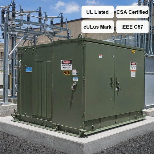
When an electrical fault or thermal overload develops inside a medium-voltage distribution substation, the speed and selectivity of primary overcurrent protection decide whether the unit trips cleanly or experiences violent tank overpressurization. For utility-scale distribution networks, commercial microgrids, and industrial facilities across the United States and Canada, the two-fuse protection package—combining an oil-immersed Bay-O-Net expulsion fuse in series with an under-oil current-limiting back-up fuse—serves as the industry-standard primary defense. However, as an experienced pad mounted transformer manufacturer, our engineering team frequently encounters submittals where improper coordination curves, mismatched crossover currents, or neglected fluid thermal derating created catastrophic blind spots in field protection.
Achieving seamless overcurrent coordination is not merely about picking catalog numbers out of a generic table; it requires plotting time-current characteristic (TCC) curves against IEEE C57.109 standards for transformer thermal and mechanical damage boundaries, accounting for 12x inrush transients, and preventing secondary arc re-ignition. Whether configuring a three phase transformer custom project for a hyperscale data center or modernizing an existing utility loop feed, proper Bay-O-Net fuse sizing and current limiting backup fuse coordination ensures robust asset protection and uninterrupted power reliability.
1. The Two-Fuse Protection Architecture: Why Single-Fuse Schemes Fail
Pad-mounted transformers connected to high-capacity medium-voltage utility distribution feeders face two distinct categories of fault currents: low-to-medium overcurrents caused by secondary bus faults, motor starting overloads, or localized winding degradation; and high-magnitude prospective short-circuit currents (often exceeding 10,000 A to 50,000 A RMS symmetrical) caused by internal primary winding flashovers.
An expulsion-type Bay-O-Net fuse operates by releasing de-ionizing gas from its internal ablative liner to extinguish low-current arcs. While exceptionally effective for low-level overcurrents and secondary fault isolation, expulsion fuses have limited interrupting ratings—typically between 1,000 A and 3,000 A RMS asymmetrical at 8.3 kV to 15.5 kV. If a Bay-O-Net fuse attempts to interrupt a 25 kA bolted primary fault alone, the massive energy release vaporizes the fuse tube, generating severe internal pressure pulses that can rupture the transformer tank or shatter the fuse holder assembly.
To eliminate this hazard, North American utilities require an under-oil partial-range back-up current-limiting fuse (such as an ELSP fuse) wired in direct electrical series on the source side of each Bay-O-Net element. The current-limiting fuse introduces an engineered silver ribbon element surrounded by high-purity silica sand. Under high fault currents, the element melts within the first sub-cycle (less than 4 milliseconds), melting the sand into non-conductive fulgurite, generating rapid arc voltage, and limiting peak let-through current to a small fraction of the prospective system fault level. By partnering with a qualified UL listed transformer supplier, consulting engineers ensure that this two-fuse coordination operates with total selectivity across the entire current spectrum.
2. Selecting Bay-O-Net Fuse Elements: Dual Sensing, Current Sensing, and Fault Sensing
Selecting the correct Bay-O-Net cartridge depends on the specific operational thermal profile and overload philosophy of the facility. Manufacturers offer three distinct classes of Bay-O-Net fuse links, each engineered for specific duty requirements:
• Current Sensing Links: These elements respond purely to root-mean-square load current flowing through the fuse link. They provide crisp overload clearing based on element I2t heating, making them ideal for standard commercial distribution where ambient fluid temperatures remain predictable and secondary breakers provide thermal backup.
• Dual Sensing Links: Engineered with a specialized dual-action alloy, Dual Sensing elements respond simultaneously to primary current and the surrounding transformer top-oil temperature. If continuous overload pushes dielectric oil temperature past 100°C, the fuse derates automatically, clearing at lower load currents to protect cellulose paper insulation from cumulative thermal aging. This dual response makes them the premier choice for unattended pad-mounted units, solar collection step-up units, and high-ambient outdoor substations.
• Dual Element / Fault Sensing Links: These links feature extended time-delay characteristics in the low-overcurrent range (to ride through 10x to 12x inrush currents for 0.1 seconds and cold-load pickup transients) combined with fast-clearing response in the intermediate fault range (5x to 10x full load current).
3. Critical Coordination Rules: Crossover Current, Inrush Withstand, and Damage Curves
Designing an airtight protection package requires satisfying three mathematical boundaries across the coordinated Time-Current Characteristic (TCC) log-log plot:
First, the Minimum Crossover Current rule dictates that the maximum clearing time of the Bay-O-Net fuse must intersect the minimum melting time of the series backup current-limiting fuse at a current level strictly below the Bay-O-Net rated maximum interrupting capacity. In our manufacturing test bay at Jiangsu Ryan Electric Co., Ltd., we validate that at any fault current above this crossover threshold, the current-limiting fuse melts and clears first, shielding the Bay-O-Net assembly from hazardous duty.
Second, the Magnetizing Inrush point requires that the primary fuse minimum melting curve lies entirely above and to the right of the transformer inrush point—defined by IEEE C57.12.00 as 12 times rated full-load current (FLA) for 0.1 seconds for units up to 2500 kVA, and 10 to 12 times FLA for larger MVA ratings. A fuse curve that cuts across this point will cause nuisance tripping during routine grid switching or black-start re-energization.
Third, the Through-Fault Withstand criterion mandates that the total clearing curve of the Bay-O-Net fuse must sit comfortably below and to the left of the IEEE C57.109 Category II and Category III frequent-fault transformer thermal and mechanical damage boundary. This guarantees that external secondary cable faults clear before conductor windings experience mechanical deformation or thermal degradation.
4. Field Experience: Solving Nuisance Tripping in High-Ambient Data Center Substations
A concrete example from our project archive illustrates how thermal nuances dictate fuse performance in demanding field environments. In late 2024, a hyperscale data center facility in Texas equipped with multiple 2500 kVA 12.47 kV - 480V/277V pad-mounted transformers reported sporadic Bay-O-Net fuse tripping on one of their primary feeder loops during peak summer operations. The site recorded zero electrical fault signatures on digital relay logs, and secondary load monitors showed steady operating currents at only 88% of rated nameplate capacity.
When our field service engineers inspected the installation, we observed two critical environmental factors: the outdoor ambient temperature had reached 43°C (109°F), and intense solar radiation on the dark olive-green enclosure had driven transformer top-oil temperatures to 82°C. The original engineering specification had selected standard Dual Sensing Bay-O-Net links sized at exactly 1.15 times full-load current without compensating for ambient fluid pre-heating. Because Dual Sensing links derate significantly as fluid temperature climbs, the element entered its melting band under normal continuous load.
Our team recalculated the coordination package, shifting to high-capacity Dual Element Fault Sensing links paired with coordinated 150 A backup current-limiting fuses and verified full UL Solutions safety compliance. This adjustment maintained full transformer through-fault thermal protection while restoring over 35% operating margin against solar-induced thermal derating. Since the retrofit, the facility has operated across continuous triple-digit summer peaks without a single nuisance trip.
5. Factory Engineering and Testing at Ryan Electric
At Jiangsu Ryan Electric Co., Ltd., fuse coordination is integrated into our core mechanical and electrical design workflows rather than treated as an afterthought accessory. Operating out of our 120,000 square meter advanced manufacturing facility with over 180 precision production sets and 37 proprietary patents, our engineering department performs computerized TCC curve overlay verifications for every unit before production release.
Since 2023, as an official joint venture partner of Eaton Corporation, Ryan Electric combines world-class North American component integration with lean manufacturing excellence. Every dead-front high-voltage compartment is engineered with standardized hot-stick operable Bay-O-Net holders equipped with internal pressure relief valves and drip guards, ensuring safe, drip-free fuse extraction during field maintenance.
Furthermore, our custom-wound coils and rigid core-clamping structures are fully short-circuit withstand tested according to IEEE C57.12.00, IEEE C57.12.28, and CSA C22.2 No. 227 standards. Whether your project demands standard mineral oil or high-fire-point natural ester fluid (FR3) compliant with U.S. Department of Energy (DOE) efficiency rules, our transformers deliver unmatched safety margins.
6. Summary and Engineering Specification Checklist for Specifiers
When preparing project specifications or reviewing submittals for North American pad-mounted transformers, ensure your engineering documentation mandates the following five core requirements:
1. Dual-Fuse Architecture: Require series combination of draw-out Bay-O-Net expulsion fuses with under-oil partial-range backup current-limiting fuses.
2. Interrupting Verification: Ensure the backup current-limiting fuse provides a minimum of 50,000 A RMS symmetrical interrupting capability at rated system voltage.
3. Explicit Crossover Coordination: Confirm that the crossover current on the submitted TCC plot occurs at least 20% below the published interrupting rating of the Bay-O-Net cartridge.
4. Thermal Fluid Derating: Specify Dual Sensing elements for high-ambient or cyclical loads only after calculating fluid thermal rise under maximum nameplate kVA and solar gain.
5. Certified Safe Isolation: Demand dead-front construction with interlocked compartments, loadbreak oil switches, and clear nameplate fuse selection stamping.
Contact Jiangsu Ryan Electric today to consult with our medium-voltage engineering team and receive detailed TCC coordination submittal packages for your upcoming substation deployments.
About the Author
David Chen is a Senior Medium-Voltage Application Engineer at Jiangsu Ryan Electric Co., Ltd., specializing in pad-mounted transformer design, IEEE/UL/CSA compliance engineering, and industrial substation protection coordination. With over 14 years of power distribution experience, he has authored technical submittals for major North American utilities, renewable EPC contractors, and global data center developers.
Table of Contents
- 1. The Two-Fuse Protection Architecture: Why Single-Fuse Schemes Fail
- 2. Selecting Bay-O-Net Fuse Elements: Dual Sensing, Current Sensing, and Fault Sensing
- 3. Critical Coordination Rules: Crossover Current, Inrush Withstand, and Damage Curves
- 4. Field Experience: Solving Nuisance Tripping in High-Ambient Data Center Substations
- 5. Factory Engineering and Testing at Ryan Electric
- 6. Summary and Engineering Specification Checklist for Specifiers
- About the Author