
 EN
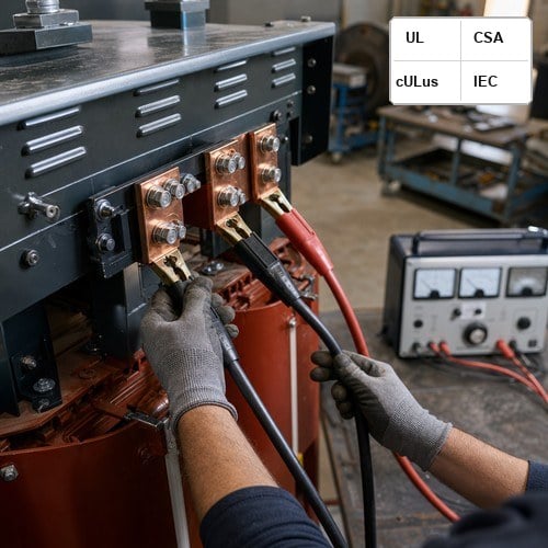
When commissioning a 115 kV to 13.8 kV autotransformer bank for a substation expansion in Alberta last autumn, the site engineering team ran into an unexpected trip during initial zero-sequence unbalance testing. The culprit was not the primary protection relay or bushing insulation; the buried delta stabilizing circuit had been sized without calculating the thermal withstand under a sustained line-to-ground fault. Sizing a tertiary winding is one of the most critical yet frequently misunderstood aspects of power transformer specification. Whether you are procuring a large auto transformer, a three-phase power transformer for renewable integration, or a multi-terminal substation unit, getting the tertiary configuration right determines whether your transformer operates reliably or suffers catastrophic core tank heating.
1. What Is a Tertiary Winding and Why Is Delta Stabilization Necessary?
In large three-phase power transformers and autotransformers connected in star-star (Wye-Wye), the magnetic and electrical symmetry of the system is vulnerable to zero-sequence currents and third-harmonic flux distortion. Without a delta-connected path, third-harmonic magnetizing currents (180 Hz on 60 Hz systems, 150 Hz on 50 Hz grids) cannot circulate. These harmonic fluxes are forced into the transformer tank walls, core clamping structures, and structural bolts, generating severe eddy current losses, acoustic noise, and localized overheating.
A delta stabilizing winding provides an enclosed, low-impedance circular loop that traps third-harmonic zero-sequence currents within the delta loop. Under international standards such as IEC 60076-1:2011 Power transformers - Part 1: General, power transformers with Wye-Wye windings can incorporate an auxiliary delta tertiary to stabilize the neutral potential, prevent neutral floating under unbalanced single-phase loads, and suppress telephone interference.
2. Loaded vs. Unloaded (Buried) Tertiary Windings: Engineering Trade-Offs
Transformer specifiers must choose between two fundamental tertiary winding architectures: loaded auxiliary tertiary windings and buried (unloaded) stabilizing windings. Each presents distinct mechanical, thermal, and protection requirements.
• Buried (Unloaded) Delta Stabilizing Windings: These windings are closed inside the main transformer tank and are not brought out to external terminal bushings, except possibly for a single test point or corner grounding terminal. Their sole role is harmonic suppression, zero-sequence flux mitigation, and neutral stabilization. Because they do not supply auxiliary substation power, their thermal rating is governed purely by short-circuit fault duration rather than continuous MVA load.
• Loaded Tertiary Windings: These windings are fully brought out through dedicated low-voltage bushings to supply station auxiliary service power, static var compensators (SVCs), synchronous condensers, or shunt reactor banks. Sizing a loaded tertiary winding requires evaluating both the continuous rated load (often 15% to 35% of the primary MVA rating) and the combined through-fault thermal/mechanical forces.
| Winding Configuration | Primary Function | Typical MVA Rating (% of Base) | Bushing & Protection Scope |
|---|---|---|---|
| Buried Delta Stabilizing | 3rd Harmonic & Neutral Stabilization | 10% - 33.3% (Fault Thermal Sized) | Internal Delta, Corner Grounded / 1 Bushing |
| Station Service Tertiary | Substation Auxiliary 480V / 4.16kV Loads | 15% - 25% Continuous Duty | 3 Full LV Bushings + Overcurrent / Breaker |
| Reactive Compensation Tertiary | Shunt Reactor / Capacitor Bank Feed | 30% - 35% Continuous Duty | 3 Heavy-Current Bushings + Surge Arresters |
3. Short-Circuit Capacity and Thermal Withstand Calculations
The single greatest failure mode of delta tertiary windings in field operation is mechanical deformation or thermal burnout during external line-to-ground faults on the transmission grid. Under a single line-to-ground (SLG) fault on the high-voltage side of an autotransformer, the zero-sequence network drives massive circulating currents through the delta loop.
According to IEC 60076-5:2006 Power transformers - Part 5: Ability to withstand short circuit, the thermal ability of a transformer winding to withstand short circuits must be verified for a standard fault duration of 2.0 seconds unless otherwise specified. The winding temperature after fault must not exceed 250°C for copper conductors with Class A insulation. In our manufacturing design practice, when the zero-sequence impedance Z0 is low, the fault current circulating in the delta can exceed 15 to 20 times the nominal winding current rating. Consequently, the minimum cross-sectional area of the tertiary winding conductor must be calculated based on the maximum clearing time of the backup ground overcurrent relay, not merely nominal full-load amperage.
Here is the practical formula applied by Ryan Electric design engineers for thermal sizing:
I_circ = (3 * V_LN) / (Z1 + Z2 + Z0_tertiary) — where Z0_tertiary incorporates the leakage reactance between the primary/secondary windings and the tertiary winding.
4. Harmonic Mitigation and Zero-Sequence Current Paths in Modern Grids
With the rapid proliferation of utility-scale solar photovoltaic plants, battery energy storage systems (BESS), and high-voltage DC (HVDC) transmission links, power quality in transmission networks has become highly complex. Modern inverter-based resources generate non-characteristic harmonics and interharmonics that can excite resonance in weakly damped sub-networks.
A properly designed delta stabilizing winding acts as a low-impedance sink for triplen harmonics (3rd, 9th, 15th, 21st harmonics). By trapping these circulating currents within the closed delta, the winding prevents harmonic voltages from inducing parasitic heating in structural steel clamp rings and the core lamination framework. For substations feeding data centers or arc furnace installations, specifying an adequately sized tertiary winding ensures that high total harmonic distortion (THD) does not compromise the expected 30-year design life of the unit.
5. Ryan Electric's Engineering & Manufacturing Advantage
At Ryan Electric (瑞安电气), transformer reliability under rigorous grid fault conditions is engineered into every component. Operating from our modern 120,000 square meter manufacturing facility equipped with over 180 advanced production and testing apparatuses and backed by 37 utility patents, our engineering team utilizes finite element method (FEM) electromagnetic simulation to map short-circuit axial and radial mechanical stresses across all winding layers.
Our engineering protocols incorporate insights from our official joint venture partnership with Eaton (伊顿) established in 2023, combining top-tier international quality systems with agile manufacturing. Every power transformer and autotransformer built in our factory undergoes comprehensive routine and type testing certified under UL, CSA, IEEE, DEKRA, CNAS, and CE standards. Whether you require a heavy-duty 230 kV autotransformer with a buried stabilizing delta or a customized 35 MVA unit with a 13.8 kV station service tertiary, Ryan Electric delivers fully certified, precision-engineered power solutions with industry-leading lead times.
6. Field Case: Substation Autotransformer Tertiary Protection Retrofit
A prominent utility operator in the Pacific Northwest commissioned Ryan Electric to supply three 100 MVA 230/115 kV single-phase autotransformer units with a 13.8 kV delta tertiary winding to replace an aging 1970s bank. The original specification called for an unloaded buried delta. However, our technical audit revealed that the regional 230 kV grid had experienced multiple high-current lightning-induced ground faults, resulting in historical tertiary failures in adjacent legacy units.
Our engineering team redesigned the tertiary winding using continuously transposed conductors (CTC) with thermally upgraded epoxy-bonded paper, increasing the short-circuit mechanical bracing strength by 40% and providing a 33.3% continuous thermal rating margin. The units were delivered and commissioned on schedule, demonstrating zero partial discharge (<10 pC at 1.5 Um) and total compliance with IEEE C57.12.00 and CSA C88 standards during factory acceptance testing.
7. Summary & Procurement Recommendations
If you are designing a substation expansion, specifying an autotransformer, or seeking technical consultation on tertiary winding and delta stabilizing winding sizing, contact Ryan Electric's senior engineering team at [email protected] or submit your Single Line Diagram (SLD) and technical specifications via our online engineering portal at ryantransformers.com. We deliver customized, certified, and cost-effective power transformer solutions worldwide.
About the Author
David Vance, Senior High-Voltage Transformer Applications Engineer at Ryan Electric. David has over 18 years of technical design and commissioning experience in medium- and high-voltage power transformers, autotransformers, and substation protection coordination across North America, the Middle East, and Asia-Pacific. He works closely with utility planners and industrial EPC contractors to deliver robust, IEEE/IEC-compliant power infrastructure solutions.
Table of Contents
- 1. What Is a Tertiary Winding and Why Is Delta Stabilization Necessary?
- 2. Loaded vs. Unloaded (Buried) Tertiary Windings: Engineering Trade-Offs
- 3. Short-Circuit Capacity and Thermal Withstand Calculations
- 4. Harmonic Mitigation and Zero-Sequence Current Paths in Modern Grids
- 5. Ryan Electric's Engineering & Manufacturing Advantage
- 6. Field Case: Substation Autotransformer Tertiary Protection Retrofit
- 7. Summary & Procurement Recommendations
- About the Author