
 EN
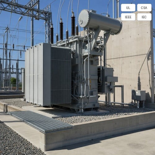
When commissioning a 34.5 kV / 138 kV 40 MVA substation transformer on a utility project in North Texas, our engineering field crew encountered a site inspection scenario that every electrical project manager should prepare for: before the regional utility inspector checked a single protection relay or primary bushing torque mark, they walked straight to the secondary oil containment pit with a tape measure. They were verifying three critical physical dimensions: the net sump volume beneath the transformer base, the gravel void ratio of the flame trap, and the exact drainage discharge path to the oil-water separator. In medium- and high-voltage substations, transformer oil containment is not merely an environmental footnote; it is the physical baseline that prevents an internal arc flash rupture or dielectric fluid leak from escalating into an uncontained environmental catastrophe and multi-million-dollar facility disaster.
Mineral insulating oil provides exceptional dielectric withstand and forced convective cooling, but a standard 40 MVA power transformer can hold upwards of 25,000 to 38,000 liters (6,600 to 10,000 gallons) of combustible hydrocarbon liquid. If a catastrophic tank rupture occurs under heavy through-fault energy, uncontained burning oil will rapidly spread across the yard, destroying adjacent buswork, tripping feeder breakers, and penetrating local groundwater aquifers. Complying with North American environmental regulations such as EPA 40 CFR 112 (SPCC Rule) and engineering standards like IEEE 980 requires precise volumetric sizing, effective flame quenching, and rigorous fire barrier separation. Here is the engineering methodology to calculate containment volume, configure flame trap rock beds, and achieve turnkey substation compliance.
Governing Standards: How IEEE 980 and EPA SPCC Define Sump Volume Calculations
The authoritative benchmark for substation spill prevention in North America is IEEE Std 980 (Guide for Containment and Control of Oil Spills in Substations), which establishes design parameters alongside the statutory requirements of EPA 40 CFR Part 112 (Spill Prevention, Control, and Countermeasure). Under these standards, secondary containment must hold the full dielectric liquid capacity of the largest protected electrical apparatus plus a mandatory safety margin for accumulated precipitation and emergency firefighting deluge.
To calculate the minimum required containment volume (V_containment), substation structural and electrical engineers must apply the combined volumetric formula:
V_containment >= 1.10 * V_oil + V_precipitation(24hr, 25yr) + V_fire_quench
Where V_oil represents 100% of the total liquid volume of the transformer (including conservator tank, radiator banks, and on-load tap changer compartments), multiplied by a 1.10 design safety factor (110% total oil volume). V_precipitation represents the total stormwater runoff collected across the catchment footprint during a 25-year return frequency, 24-hour storm event (typically 120 mm to 200 mm depending on regional NOAA Atlas 14 precipitation frequency estimates). V_fire_quench accounts for active deluge water from fixed water spray or deluge foam systems operating continuously at design density (typically 10.2 L/min/m2 for 15 minutes per NFPA 15).
Flame Quenching Mechanics: Sizing Crushed Rock Beds and Void Ratios
A common pitfall in substation foundation design is failing to account for stone displacement volume inside the oil collection basin. When burning transformer oil discharges into an active containment pit, the purpose of the gravel bed is twofold: to quench the flames by rapidly cooling the oil below its flash point (typically 145 °C to 160 °C for mineral oil) and to cut off atmospheric oxygen circulation. However, gravel occupies physical space, significantly reducing the liquid holding capacity of the sump.
According to IEEE 980, the effective liquid retention capacity of a rock-filled basin depends directly on the void ratio (e_void) of the aggregate. Standard angular crushed rock provides a void ratio between 35% and 40%, with 38% (0.38) serving as the standard design conservative baseline. Engineers must specify clean, uniformly sized, 1.5-inch (38 mm) washed crushed stone free of stone dust and clay fines. The minimum depth of the rock layer must not be less than 300 mm (12 inches) over the entire containment floor.
If the total volume occupied by stone is V_stone_gross, the actual net oil storage volume inside the stone matrix is only V_stone_net = V_stone_gross * 0.38. For example, if a transformer pit has gross excavation dimensions of 8.0 m x 6.0 m x 0.6 m deep (28.8 m3 gross volume) filled entirely with 1.5-inch gravel, the true net liquid retention capacity before overflowing is only 28.8 * 0.38 = 10.94 m3 (10,944 liters). Overlooking this displacement factor leads directly to undersized sumps that violate EPA SPCC site audits.
To help EPC design teams select the optimal civil layout for various substation footprints, the comparison matrix below summarizes the three primary transformer oil containment architectures:
| Containment Architecture | Footprint & Civil Cost | Flame Quenching Efficiency | Stormwater Handling | Best Application Scenario |
|---|---|---|---|---|
| Integrated Pit Containment (Direct Sump with Rock Bed) | Compact footprint directly below transformer; Moderate excavation cost | High; 300 mm washed crushed stone extinguishes burning oil in < 15 seconds | Relies on gravity drain or sump pump with optical oil sensors | Single-unit industrial substations and space-constrained urban yards |
| Remote Holding Sump System with Gravity Trench | Minimal pad footprint; Requires dedicated underground tank & sloped trenches | Very High; Oil drains immediately through flame trap grating to sealed tank | Excellent; Dedicated oil-water separator handles continuous drainage safely | Multi-transformer utility substations (2 to 4 large power transformers) |
| Barrier Berm Containment with Oil-Stop Valves | Large perimeter footprint; Low concrete forming cost, uses earthen dikes | Moderate; Requires extensive gravel layer across wide retention basin | High surge capacity; Uses self-sealing hydrophobic oil-stop filter valves | Rural transmission substations and large-scale solar farm step-up yards |
Fire Barrier Separation and Spatial Clearances (NFPA 850 & IEEE 979 Compliance)
When multiple medium- or high-voltage transformers operate in parallel, secondary liquid containment must be paired with structural fire barrier separation. Under NFPA 850 (Recommended Practice for Fire Protection for Electric Generating Plants and High Voltage Direct Current Converter Stations) and IEEE 979, outdoor oil-filled transformers containing more than 3,785 liters (1,000 gallons) of oil require mandatory spatial separation or fire-rated barrier walls to prevent thermal radiation damage to adjacent electrical assets.
If adjacent transformer centerlines are spaced less than 7.6 m to 15.2 m (25 ft to 50 ft) apart depending on total oil volume and building proximity, a reinforced concrete or masonry fire barrier wall must be installed. Key engineering specifications include:
1. Fire Resistance Rating: The barrier wall must possess a certified minimum 2-hour fire endurance rating tested under ASTM E119 / UL 263.
2. Height and Extension: The fire wall must extend vertically at least 0.3 m (1 ft) above the highest point of the transformer conservator tank, pressure relief device (PRD), and high-voltage bushings. Horizontally, the wall must project at least 0.6 m (2 ft) beyond the outer extremities of the transformer radiators and tank edges.
3. Structural Independence: The fire barrier wall must have independent concrete foundations capable of withstanding local wind shear (ASCE 7) and seismic shock (IEEE 693 high seismic qualification) without relying on the transformer foundation for lateral stability.
Drainage Engineering: Automated Oil-Water Separation and Zero-Discharge Protocols
A containment sump that fills with rainwater is a containment sump that has lost its safety capacity. Under North American Clean Water Act provisions enforced through EPA SPCC Secondary Containment Calculations, substations cannot discharge untreated stormwater into municipal drains, drainage ditches, or soil if the effluent contains visible oil sheen or free hydrocarbon concentrations exceeding 10 ppm to 15 ppm.
Modern substation engineering utilizes two proven automated drainage methodologies to ensure continuous compliance:
- Gravity Coalescing Oil-Water Separators (OWS): Rainwater and potential minor washings gravity-flow through a minimum 1.5% to 2.0% sloped underground pipe into an external corrugated plate interceptor (CPI). The coalescing matrix forces microscopic oil droplets to coalesce and float into an internal oil retention chamber while clean water discharges continuously.
- Hydrophobic Oil-Stop Valves and Solidification Cartridges: For standalone pad-mounted and medium-voltage distribution units, self-closing discharge valves utilize polymer technology that allows clean rainwater to pass unimpeded. The moment liquid hydrocarbons make contact with the polymer cartridge, it chemically solidifies within seconds, forming an impenetrable barrier that seals the drain port completely.
The Ryan Electric Engineering Edge: Factory Tank Integrity and Turnkey Integration
At Ryan Electric, we understand that effective secondary containment begins at the primary equipment boundary: the transformer mechanical tank itself. Across our 120,000 m2 smart manufacturing facility equipped with 180+ advanced fabrication machines and 37 core patents, our oil-immersed power transformers and pad-mounted substation units undergo rigorous structural stress analysis and 100% positive-pressure helium leak testing to exceed IEEE C57.12.00, CSA C22.2, and UL standards.
Building on our official joint venture manufacturing partnership with Eaton since 2023, Ryan integrates precision engineering into every unit submittal drawing. Every power transformer nameplate and Factory Acceptance Test (FAT) dossier explicitly details certified total oil mass (kg), precise liquid volume in liters and gallons, tank rupture pressure tolerance (kPa), and base drainage nozzle locations. This empowers EPC structural teams to model transformer oil containment sumps, calculate stone void ratios, and design fire barrier separation layouts with zero design guesswork.
Substation Commissioning Case: 45 MVA Solar PV Substation in West Texas
A prominent utility-scale EPC contractor in West Texas recently deployed two units of Ryan 34.5 kV / 138 kV 45 MVA natural ester (FR3) oil-immersed step-up transformers for a 200 MW solar-plus-storage generation facility. The site was subject to stringent EPA SPCC oversight due to a protected seasonal watershed located 400 meters down-gradient.
Ryan engineering provided a customized turnkey containment package: complete 3D CAD civil anchor interface drawings, calculated 24-hour storm runoff coefficients based on local NOAA data, and coordinated dual remote sumps equipped with 1.5-inch washed crushed stone flame trap beds. During on-site commissioning, the full containment system passed hydraulic zero-leakage testing on first inspection, achieving complete utility sign-off and energizing the 200 MW interconnection 14 days ahead of scheduled commercial operation.
Engineering Verification Checklist Before Pouring Substation Concrete
Before releasing civil foundation drawings for construction, verify these 5 critical parameters with your electrical and structural design teams:
1. Total Fluid Volume Baseline: Confirm the exact oil volume of the transformer (including conservator and OLTC) from the manufacturer submittal drawing, applying the 1.10 multiplier.
2. Gravel Void Allowance: Ensure the rock containment sump volume calculation explicitly applies a maximum 0.38 void ratio rather than gross volumetric space.
3. Stormwater Inflow: Incorporate the 25-year 24-hour peak precipitation event for the specific geographical coordinate.
4. Barrier Geometry: Verify that fire walls exceed top bushing and PRD heights by at least 0.3 m and radiator edges by 0.6 m.
5. Automatic Drainage Safeguards: Specify fail-safe oil-stop valves or OWS units certified to discharge < 10 ppm hydrocarbon effluent.
Need certified submittal drawings, foundation loading diagrams, or custom liquid-filled power transformer designs for your next utility, data center, or renewable substation project? Contact the Ryan Electric substation engineering team today to review custom specifications and lead-time optimization.
About the Author
David Vance is a Senior Substation Application Engineer at Ryan Electric with over 16 years of experience in high-voltage power transformer design, substation civil-electrical integration, and IEEE / CSA compliance engineering. He works closely with North American EPC contractors, municipal utilities, and industrial developers to deliver high-reliability power transformer solutions tailored to harsh grid and environmental operating conditions.
Table of Contents
- Governing Standards: How IEEE 980 and EPA SPCC Define Sump Volume Calculations
- Flame Quenching Mechanics: Sizing Crushed Rock Beds and Void Ratios
- Fire Barrier Separation and Spatial Clearances (NFPA 850 & IEEE 979 Compliance)
- Drainage Engineering: Automated Oil-Water Separation and Zero-Discharge Protocols
- The Ryan Electric Engineering Edge: Factory Tank Integrity and Turnkey Integration
- Substation Commissioning Case: 45 MVA Solar PV Substation in West Texas
- Engineering Verification Checklist Before Pouring Substation Concrete
- About the Author