
 EN
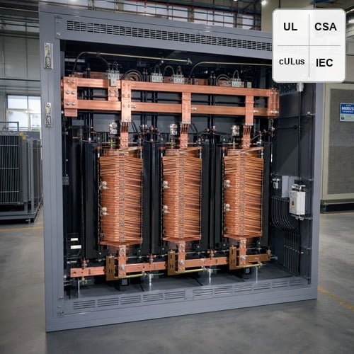
Switch-mode power supplies, variable frequency drives (VFDs), server power units, and LED driver ballasts draw electrical current in sharp, discontinuous pulses rather than smooth sinusoidal waves. When hundreds of these non-linear loads operate across commercial buildings and hyperscale server halls, severe harmonic distortion enters the low-voltage distribution network. Standard distribution transformers operating under these conditions face extreme thermal stress, excessive stray losses, and dangerously overheated neutral conductors.
Specifying a harmonic mitigating transformer (HMT) is the primary engineering solution to eliminate harmonic currents at the magnetic core level. Rather than simply tolerating elevated winding temperatures, a modern harmonic mitigating transformer utilizes internal phase-shifting electromagnetic cancellation to treat triplen, 5th, 7th, 11th, and 13th harmonic currents before they propagate back into the upstream electrical grid. This comprehensive guide breaks down the electromagnetic physics of HMTs, compares them with standard K-factor units, evaluates phase-shifting winding topologies, and provides step-by-step sizing rules for data center power quality compliance.
The Physics of Non-Linear Heating: Why Standard Distribution Transformers Fail
Non-linear load currents generate high-frequency harmonic spectra categorized by their sequence components: positive sequence (1st, 4th, 7th, 10th...), negative sequence (2nd, 5th, 8th, 11th...), and zero sequence (3rd, 9th, 15th, 21st...). In standard delta-wye distribution transformers, positive and negative sequence harmonics induce intense electromagnetic eddy currents in the primary and secondary copper conductors. Because winding eddy current losses (P_EC) scale proportionally with the square of the harmonic order multiplied by the square of the harmonic current, high-frequency harmonic currents dramatically accelerate transformer thermal degradation.
Zero-sequence harmonics, commonly known as triplen harmonics (dominated by the 3rd harmonic at 180 Hz in 60 Hz grids and 150 Hz in 50 Hz grids), present an even more dangerous operational hazard. Unlike balanced fundamental currents that sum to zero at the neutral junction, triplen harmonic currents from all three phases are completely in phase with each other. Consequently, they add arithmetically in the shared neutral conductor, frequently causing neutral currents to reach 140% to 200% of the rated phase current. In unmitigated facilities, this arithmetic addition causes catastrophic neutral lug overheating, transformer core saturation, and severe voltage waveform flat-topping.
K-Factor Transformer vs HMT: Managing Heat vs Eliminating Distortion
Many electrical engineering specifications routinely call for K-factor rated transformers (such as K-4, K-13, or K-20) when non-linear loads are expected. However, understanding the fundamental distinction in K-factor transformer vs HMT technology is essential for long-term power system reliability. A K-factor transformer is fundamentally a passive survivor: it is designed with oversized neutral conductors, paralleled smaller-gauge winding conductors to reduce skin-effect losses, and a heavier magnetic core to dissipate excess heat without burning out. Crucially, a K-factor transformer does not eliminate harmonic currents; it allows all harmonic distortion to flow straight through to the upstream switchgear and utility service entrance.
In contrast, a harmonic mitigating transformer uses patented phase-shifting winding geometries and secondary zig-zag connections to create counteracting magnetic fluxes. By forcing harmonic currents of specific phase angles into magnetic opposition, the HMT achieves genuine triplen harmonics cancellation right inside the transformer tank. Voltage distortion (THD_V) is suppressed at the secondary bus, and upstream current distortion (THD_I) is drastically reduced, ensuring strict compliance with IEEE 519-2022 recommendations and the U.S. Department of Energy (DOE) Transformer Efficiency Regulations without requiring expensive, resonance-prone active harmonic filters.
| Performance Parameter | Standard Distribution Transformer | K-Factor Transformer (K-13 / K-20) | Harmonic Mitigating Transformer (HMT) |
|---|---|---|---|
| Primary Harmonic Treatment | None (Derating required) | Thermal management only (No cancellation) | Active electromagnetic flux cancellation |
| Triplen Harmonics (3rd, 9th) | Trapped in primary delta / Overheats core | Trapped in primary delta / Heavy heating | Cancelled in secondary zig-zag winding |
| 5th & 7th Harmonics | Passes through upstream | Passes through upstream | Cancelled via 0° / 30° phase-shifted pairs |
| Secondary Voltage THD | High (8% to 15% flat-topping) | High (7% to 12% flat-topping) | Low (< 3.0% clean sinusoidal output) |
| Neutral Bus Sizing | 100% rated | 200% rated | 200% rated with near-zero neutral return |
| System Energy Efficiency | Degrades rapidly under non-linear load | Moderate (Higher no-load & load losses) | Superior (Substantially reduced eddy losses) |
Phase-Shifting Topologies: Zero-Degree Zig-Zag and Angular Displacement Pairs
The core operational mechanism of an HMT relies on precise winding phase displacement. For single-unit installations supplying single-phase non-linear IT equipment, a zero-degree phase-shift HMT employs a delta primary coupled with a zig-zag (interconnected star) secondary winding. Each secondary phase winding consists of two equal coil sections wound in opposite magnetic directions on adjacent core limbs. When triplen harmonic currents enter the zig-zag neutral, the equal and opposite ampere-turns produce magnetic fluxes that cancel each other out completely within the core. As a result, triplen harmonic currents cannot induce secondary zero-sequence flux, preventing circulating currents in the primary delta and keeping the primary feeder free of 3rd harmonic distortion.
For larger industrial facilities and data center pod distribution, advanced harmonic mitigation utilizes paired phase shifting transformer topologies. By deploying pairs of transformers with an angular phase displacement of 30° between their secondaries (for example, Unit A with a 0° phase shift and Unit B with a -30° or +30° phase shift), the 5th and 7th harmonic currents generated by load group A and load group B are 180° out of phase when they sum at the common primary switchboard. This phase cancellation eliminates up to 90% of the 5th and 7th harmonics from the upstream utility feed. Furthermore, utilizing four-unit configurations with 15° phase increments (0°, +15°, +30°, +45°) enables simultaneous cancellation of 5th, 7th, 11th, and 13th harmonics, providing ultra-clean, quasi-24-pulse equivalent power quality at a fraction of the cost of dedicated active front ends.
Engineering Sizing and Specification Checklist for Data Center Power Quality
When preparing procurement specifications for an HMT, electrical system designers must evaluate five critical technical parameters to ensure maximum harmonic mitigation performance:
1. Load K-Factor and Harmonic Spectrum Audit: Obtain the expected Total Harmonic Distortion (THD_I) and harmonic profile. If triplen harmonics exceed 25% of the phase fundamental current, specify a zig-zag secondary configuration with a minimum 200% rated neutral busbar.
2. Phase-Shift Angle Matching: When designing paired distribution systems, ensure identical kVA sizing and equal load distribution between the 0° and 30° phase-shifted units. Any load imbalance will directly reduce the percentage of 5th and 7th harmonic cancellation.
3. Impedance Tolerance and Short-Circuit Symmetry: Specify standard impedance between 4.0% and 6.0% with a tight tolerance of ±5% across all units to maintain balanced fault currents and precise angular phase separation under varying load conditions.
4. Insulation System and Thermal Margin: Insist on a 220°C (Class 220) UL-listed insulation system with a low 80°C or 115°C temperature rise rating. The lower operating temperature provides exceptional thermal reserve, substantially extending transformer service life in continuous 24/7 mission-critical operations.
5. Core Material and Magnetic Flux Density: Specify high-permeability, grain-oriented silicon steel (M4/M3 or laser-treated grades) designed to operate at conservative magnetic flux densities (typically 1.45 to 1.55 Tesla), preventing core saturation during transient overvoltages and high harmonic voltage components.
Ryan Electric Manufacturing Excellence: Certified Quality for Mission-Critical Loads
As an Eaton official joint-venture partner since 2023, Ryan Electric manufactures high-performance dry-type and liquid-filled harmonic mitigating transformers engineered for the world's most demanding data centers, renewable microgrids, and industrial automation facilities. Operating from our state-of-the-art 120,000 m² factory equipped with 180+ sets of precision manufacturing machinery and holding 37 proprietary transformer technology patents, we build every HMT with rigorous mechanical robustness and exceptional electrical efficiency.
In our factory testing bay, when testing dual-output phase-shifting transformers for a hyperscale data center client in Southeast Asia, measuring secondary voltage displacement on an oscilloscope and verifying 0.1° angular accuracy before shipping is part of our standard quality assurance protocol. Every Ryan HMT undergoes 100% routine testing according to IEEE C57.12.01, IEEE C57.110, UL 1561, and CSA C22.2 standards, including full-spectrum harmonic load simulation, winding resistance, partial discharge analysis, and precise angular phase displacement verification.
Real-World Case Study: 2.5 MVA Data Center Power Quality Retrofit
A tier-III enterprise colocation facility experienced severe neutral conductor overheating and frequent UPS synchronization alarms on their low-voltage power distribution units (PDUs). The original installation utilized standard K-13 dry-type transformers, where total voltage harmonic distortion (THD_V) routinely reached 8.4% and neutral return current exceeded 168% of nominal phase current under 70% IT rack load.
Ryan Electric engineered and supplied six 500 kVA harmonic mitigating dry-type transformers configured in paired 0° and 30° phase-shifting topologies with zig-zag secondaries. Following commissioning, the facility achieved dramatic power quality improvements: secondary voltage THD dropped from 8.4% to 2.1%, neutral return current plummeted by 86% to well under 25A, and overall transformer operating temperature decreased by 18°C. The installation achieved full compliance with IEEE Standards Association power quality recommendations, eliminating nuisance breaker tripping and recovering over 45 kW in continuous waste heat losses.
Empower Your Facility with Advanced Harmonic Mitigation
Harmonic currents should never compromise your facility's operational uptime, energy efficiency, or equipment longevity. By integrating engineered harmonic mitigating transformers into your power distribution design, you eliminate harmonic heating at the root, protect sensitive electronic equipment, and ensure compliance with global power quality codes. Contact our engineering team today to review your electrical single-line diagrams, simulate harmonic cancellation profiles, and receive a customized transformer quotation built to UL, CSA, and IEEE standards.
About the Author: The Ryan Electric Engineering Technical Editorial Team consists of senior transformer design specialists and high-voltage power distribution engineers with decades of experience in electromagnetic simulation, harmonic mitigation, and mission-critical power system architecture. Ryan Electric delivers certified dry-type, pad-mounted, and oil-immersed transformers to premier global clients across North America, Southeast Asia, and the Middle East.
Table of Contents
- The Physics of Non-Linear Heating: Why Standard Distribution Transformers Fail
- K-Factor Transformer vs HMT: Managing Heat vs Eliminating Distortion
- Phase-Shifting Topologies: Zero-Degree Zig-Zag and Angular Displacement Pairs
- Engineering Sizing and Specification Checklist for Data Center Power Quality
- Ryan Electric Manufacturing Excellence: Certified Quality for Mission-Critical Loads
- Real-World Case Study: 2.5 MVA Data Center Power Quality Retrofit
- Empower Your Facility with Advanced Harmonic Mitigation