
 EN
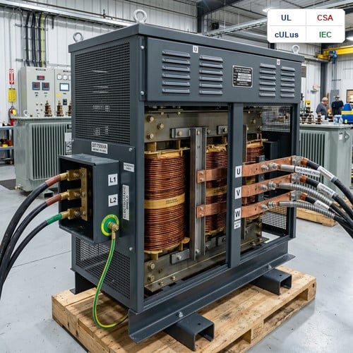
When an industrial facility installs a high-horsepower variable frequency drive (VFD), maintenance managers often expect seamless speed modulation and immediate energy savings. However, within weeks of commissioning, unshielded standard distribution transformers feeding these drives frequently experience mysterious thermal overloads, nuisance ground-fault trips, and insulation breakdown. The root cause lies in a fundamental mismatch: standard distribution units are built for pure 50/60 Hz sinusoidal power, while non-linear 6-pulse and 12-pulse rectifier front-ends generate severe harmonic distortion, steep dv/dt voltage transients, and common-mode electrical noise. Specifying a dedicated drive isolation transformer is the essential engineering safeguard that decouples the upstream electrical grid from harsh drive-induced disturbances.
Unlike generic dry-type units, a true VFD isolation transformer incorporates heavy-duty electrostatic shielding, custom magnetic flux de-rating, and robust mechanical bracing. It handles harmonic spectrum currents without exceeding thermal limits while attenuating high-frequency noise that destroys motor bearings and sensitive programmable logic controllers (PLCs).
1. Understanding the Electrical Stress: SCR Commutation Notching and Harmonic Heating
Variable frequency drives convert AC utility power into a regulated DC bus voltage using silicon-controlled rectifiers (SCRs) or diode bridges before inverting it back to variable-frequency AC. During this rectification process, SCR commutation briefly creates line-to-line short circuits during diode conduction transfer. This phenomenon, known as SCR commutation notching, carves sharp notches into the supply voltage waveform. On a standard utility transformer, these high-frequency notches excite internal winding capacitances, producing severe voltage ringing that rapidly deteriorates standard turn-to-turn insulation.
Beyond voltage notching, non-linear drive rectifiers draw non-sinusoidal harmonic currents. A conventional 6-pulse drive injects prominent 5th, 7th, 11th, and 13th harmonic currents back into the transformer windings. Because winding eddy-current losses escalate with the square of the harmonic frequency (Ph = Pec * h^2), a 5th harmonic current causes 25 times more eddy-current heating than an equivalent 60 Hz fundamental current. According to the foundational engineering principles outlined in IEEE Standard C57.18.10 for Semiconductor Power Rectifier Transformers, transformers feeding converter loads require specialized copper transposition, de-rated core flux densities (typically 1.35 to 1.45 Tesla rather than standard 1.7 Tesla), and high-temperature Class 220°C insulation systems to withstand localized harmonic hot-spots.
2. Key Sizing Criteria: K-Factor Rating and Impedance Selection for Drive Isolation Transformers
Properly sizing a drive isolation transformer requires evaluating two critical parameters: the thermal K-factor rating and the percent impedance (%Z). Selecting the correct K-factor ensures the transformer dissipates harmonic eddy losses without exceeding its rated temperature rise (e.g., 80°C or 115°C rise over a 40°C ambient). For standard 6-pulse VFD installations without active harmonic filters, a K-13 rating is the industry baseline. For heavily loaded drives operating in continuous heavy-duty industrial cycles or older DC drive systems with severe phase-angle firing, a K-20 or K-30 rated unit is necessary.
Impedance matching is equally vital. A drive isolation transformer designed with 5% to 8% internal impedance acts as an integrated line reactor, delivering two major benefits:
- Fault Current and Inrush Limitation: It limits prospective short-circuit currents and dampens drive turn-on inrush, shielding downstream SCRs and IGBT modules from catastrophic thermal destruction.
- THD Reduction: It smooths current draw, reducing Total Harmonic Distortion (THD) at the point of common coupling (PCC) to assist compliance with utility limits, aligned with federal efficiency standards published by the U.S. Department of Energy (DOE).
| Parameter / Design Feature | Standard General-Purpose Transformer | VFD Drive Isolation Transformer |
|---|---|---|
| Core Flux Density | Nominal 1.65 – 1.72 Tesla (Core saturation at peak harmonic voltages) | De-rated to 1.35 – 1.45 Tesla (Handles DC bias & high dv/dt without saturation) |
| Electrostatic Shielding | None or single-layer floating shield | Grounded copper electrostatic shield between primary & secondary |
| Harmonic Handling (K-Factor) | K-1 (Designed purely for linear 50/60 Hz sinusoidal loads) | K-13, K-20, or K-30 rated (Transposition conductors & split multi-strand foil) |
| Common-Mode Noise Attenuation | < 10 dB capacitive coupling attenuation | > 60 dB to 80 dB attenuation via grounded Faraday shield |
| Mechanical Bracing | Standard short-circuit withstand (2-3 seconds at nominal) | Reinforced axial & radial bracing (Withstands repeated drive fault surges) |
| SCR Commutation Notching | Notching induces heavy insulation stress & capacitive flashovers | Integrated impedance (5% – 8%) absorbs commutation notches and limits di/dt |
3. Electrostatic Shielding: Eliminating Common-Mode Noise and Bearing Currents
One of the most devastating issues in modern automated plants is common-mode voltage generated by the high switching frequencies (2 kHz to 16 kHz) of drive IGBTs. This high-frequency common-mode noise couples capacitively across standard transformer windings, traveling upstream to corrupt SCADA communications and downstream through motor shafts, where it discharges across motor bearings—causing electrical fluting, premature bearing failure, and unexpected motor burnouts.
A professionally engineered VFD isolation transformer incorporates an electrostatic Faraday shield—a continuous sheet of copper placed between the primary and secondary windings and securely bonded to the transformer grounding bus. This grounded copper barrier intercepts inter-winding capacitive coupling, attenuating common-mode electrical noise by 60 dB to 80 dB. In our factory testing bays, inserting a grounded electrostatic shield reduces high-frequency transient transmission to less than 0.1% of the source amplitude, safeguarding both upstream sensitive instrumentation and downstream connected motors.
4. Field Experience: Troubleshooting Texas Municipal Water Treatment Pumping Station
Field experience consistently demonstrates that generic distribution units cannot survive demanding drive duty. During a commissioning project at a municipal water treatment facility in Texas, four 400 HP centrifugal pumps powered by 6-pulse VFDs were initially connected directly to standard 480V/480V delta-wye distribution transformers. Within three months of continuous operation, two transformers experienced severe thermal tripping, and the plant's PLC telemetry began reporting spurious communication drops during pump ramp-up.
When our engineering team conducted an on-site power quality audit, we measured 28.4% current THD and substantial 5th/7th harmonic content, which drove the core temperature beyond 165°C. We replaced the standard transformers with custom-engineered K-13 rated drive isolation transformer units featuring 6.5% impedance and dual electrostatic shields. Immediately upon energization, transformer operating temperatures dropped to a stable 72°C rise, common-mode noise on the 24V DC control bus was completely eliminated, and the facility has operated with 100% reliability for over three years.
5. Ryan Electric Advantage: Custom Engineered Solutions and Eaton JV Backing
At Ryan Electric, we specialize in the custom engineering and manufacturing of heavy-duty drive isolation transformers for the most demanding global industrial sectors, including mining hoists, marine propulsion, water infrastructure, and data center chillers. With our 120,000 m² state-of-the-art manufacturing facility, 37 proprietary transformer patents, and over 180 precision production machines, we deliver customized magnetic solutions that exact application specifications require.
As an official joint venture partner with Eaton since 2023, Ryan Electric combines tier-one international quality assurance systems with agile manufacturing. Whether you require a specialized dry-type unit, a liquid-immersed pad mounted converter transformer, or a three phase transformer custom design built to IEC, IEEE, or CSA standards, our engineering team tailors winding geometry, core flux margins, and thermal dissipation systems for optimal operational life. As a trusted UL listed transformer supplier, every unit undergoes rigorous Factory Acceptance Testing (FAT), including full harmonic load-loss simulation and impulse withstand testing prior to dispatch.
6. Specifying Your Drive Isolation Transformer: 4-Point Engineering Checklist
When preparing an RFQ or procurement specification for a drive isolation transformer, include the following parameters to ensure optimal field performance and long-term reliability:
- 1. Drive Topology & Rectifier Configuration: Specify whether the front-end is 6-pulse, 12-pulse, 18-pulse, or Active Front End (AFE) PWM, including the full expected harmonic current spectrum.
- 2. K-Factor Rating: Designate minimum K-13 for standard 6-pulse industrial drives, and K-20/K-30 for severe cyclical loads or multi-motor common DC bus systems.
- 3. Impedance & Voltage Taps: Specify 5.0% to 8.0% impedance to optimize harmonic mitigation and short-circuit withstand, with ±2 x 2.5% full-capacity primary taps.
- 4. Electrostatic Shielding & Thermal Class: Mandate a full copper electrostatic Faraday shield grounded to the enclosure frame, paired with a Class 220°C insulation system designed for 80°C or 115°C rise.
About the Author
David Vance, Senior Application Engineer at Ryan Electric. David holds a B.S. in Electrical Engineering with over 16 years of experience in medium and low voltage power distribution, specialized converter transformer design, and industrial harmonic mitigation across North American and European industrial projects.
Table of Contents
- 1. Understanding the Electrical Stress: SCR Commutation Notching and Harmonic Heating
- 2. Key Sizing Criteria: K-Factor Rating and Impedance Selection for Drive Isolation Transformers
- 3. Electrostatic Shielding: Eliminating Common-Mode Noise and Bearing Currents
- 4. Field Experience: Troubleshooting Texas Municipal Water Treatment Pumping Station
- 5. Ryan Electric Advantage: Custom Engineered Solutions and Eaton JV Backing
- 6. Specifying Your Drive Isolation Transformer: 4-Point Engineering Checklist
- About the Author