
 EN
EN
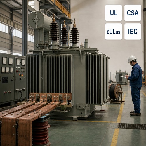
Two 2,000 kVA units landed at the same substation last spring. Same voltage ratio, same 208Y/120 V secondary, both UL listed on the nameplate. The commissioning crew closed the tie breaker to parallel them, and inside two hours the winding temperature alarm on one unit tripped. Nothing was defective. One transformer had been bought at 5.75% impedance, the other at 4.0% – and when two units share a bus, load divides inversely with impedance. The 4.0% unit was carrying roughly 59% of the total while its partner idled at 41%. It was doing the work of a bigger transformer, and it was heating up like one.
That single percentage point is why transformer impedance deserves more attention than the one line it usually gets in a purchase order. Percent impedance decides three things at the same time: how much fault current your switchgear has to interrupt, how much voltage you lose between no load and full load, and whether two units can run in parallel without one of them carrying the other's share. Get it wrong on paper and the mistake surfaces in the field, in the arc-flash study, or at the commissioning meeting.
What Transformer Impedance Actually Measures
Percent impedance is measured with one winding short-circuited and a variable voltage applied to the other. Raise that voltage until rated current flows, then express the applied voltage as a percentage of rated voltage. A 5.75% transformer needs 5.75% of its rated voltage to drive rated current through a bolted short. Most of that impedance comes from leakage flux that does not link both windings, plus the resistance of the copper itself.
The procedure is standardised. Impedance and load loss measurement sit in IEEE C57.12.90 for liquid-immersed units, published on the IEEE Standards Association page for the test code; the general requirements for power transformers, including how short-circuit impedance is declared, are set out in IEC 60076-1. Both call for the figure to be referenced to a stated current and a reference temperature, because the resistance component – and therefore the total – moves as the windings heat up.
The typical bands look like this:
| Transformer class | Typical impedance (%Z) | What sets the value |
| Dry type, up to 1,000 kVA | 4% - 6% | Fault current limitation against voltage drop |
| Liquid-immersed distribution, 500 - 2,500 kVA | 4% - 6% | Utility fault-current coordination |
| Medium power, 5 - 20 MVA | 6% - 10% | Secondary switchgear rating, system stiffness |
| Large power, above 20 MVA | 8% - 16% | Fault current, unit cost, voltage regulation |
Treat that as a range, not a rule. Two suppliers can quote the same kVA at opposite ends of it and both be right. The number you receive is a design compromise agreed at specification stage, not something to discover at the factory acceptance test.
Why Percent Impedance Sets Your Available Short-Circuit Current
Here is the arithmetic most buyers never see. On a per-unit basis the transformer's impedance defines the current available at the secondary: Isc equals rated secondary current divided by impedance in per unit. Take a 2,000 kVA, 480 V three-phase unit. Rated secondary current is 2,406 A. At 5.75% impedance a bolted three-phase fault on the secondary can reach about 41,800 A. At 4.0% the same transformer reaches about 60,150 A.
That 1.75 point difference moves the available short-circuit current by roughly 18 kA. It is the difference between two classes of low-voltage switchgear, two bus bracing requirements and two incident-energy results in the arc-flash study. Contractors in Texas and Alberta ask us about this constantly, usually after a coordination study has come back with equipment they cannot buy at the price they assumed.
Impedance also has a shape. The percentage is the vector sum of a resistance component, which produces the load loss, and a reactive component, which stores leakage energy. The ratio between them determines how asymmetric the first few cycles of fault current will be, and the breaker you select has to close on that asymmetry. Two transformers with the same impedance value and different ratios are not interchangeable in a fault study.
Voltage Regulation: The Other Half of the Same Trade-Off
Impedance buys fault-current limitation and charges you in voltage regulation. Under load, terminal voltage sags by an amount that scales with the impedance and the load current, and the drop is roughly the resistance component times the cosine of the load angle plus the reactive component times the sine. A stiffer transformer – lower impedance – holds its secondary voltage better, which is exactly what a motor-heavy plant or a data hall with a narrow voltage window wants.
Push impedance down and the secondary stays flat, but available fault current climbs and so does the cost of every downstream device. Push impedance up to tame the fault current and the same loads now see more voltage drop and more reactive loss. No single winding geometry gives you both, which is why this figure belongs in the specification discussion rather than in a default template.
The standards also accept that the declared value is not exact. IEC 60076-1 sets out how short-circuit impedance is specified and what tolerance applies to the declared figure, and those tolerances are wide enough that a unit can legitimately test a few tenths of a percent away from the number in the contract. If paralleling is in your future, write the tolerance band down instead of assuming the nameplate is exact.
Paralleling: Where One Percentage Point Becomes Real Money
Parallel operation has four conditions, and impedance is only one of them: matched voltage ratio and tap position, the same vector group and phase displacement, the same phase sequence, and impedance that matches in both magnitude and reactive-to-resistive ratio.
When the impedance of the two units does not match, load divides inversely with it. The commissioning example above is the textbook case. Run a 4.0% and a 5.75% unit to 90% of their combined capacity and the low-impedance unit is already past its own rating while the other still has headroom. The higher-impedance unit never gets tapped out; its partner carries the pair.
Most utility and industrial specifications cap the impedance difference between units intended to operate in parallel at 10%, and the caution is earned, because the imbalance grows quickly as the gap widens. If a future tie between two transformers is even possible, put the impedance band in both purchase orders at the same time. Sourcing a matching unit five years later is where these projects get expensive.
How to Specify Impedance Without Boxing Yourself In
A transformer impedance figure is a specification input, not a test result to be discovered later. Seven items belong in the impedance section of an RFQ, and most of them cost nothing to state:
- Impedance value and tolerance. State the nominal figure and the acceptable band, both at rated current.
- Reference tap. Impedance changes across the tap range, so say which tapping the value applies to and ask for the extreme-tap values as well.
- Reference temperature. Resistance is temperature dependent, and so is the number you are specifying.
- Downstream fault rating. Give the supplier the switchgear rating and let them propose the impedance window that fits it.
- Voltage regulation requirement at the design load power factor.
- Paralleling intent. If a second unit may be added later, say so now and specify the matching band.
- Report requirements. Ask for measured impedance and load loss in the routine test report, not only in the design calculation.
That last item matters more than it looks. On more than one project we have watched a parallel pair refuse to share load because the two routine test reports had never been placed side by side before commissioning.
How Ryan Electric Measures and Reports Impedance
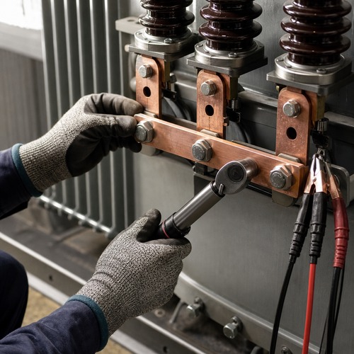
Every unit that leaves our test bay has its impedance and load loss measured at rated current and reported against the declared value, at the tap positions actually supplied rather than only the principal tap. Where a customer has specified a matching band for future paralleling on a custom three-phase transformer, the same report carries the extreme-tap figures so the commissioning engineer can check the pair before energising.
We build in a 120,000 square metre facility with more than 180 sets of production and test equipment and 37 patents, and we hold UL, CSA, IEEE, DEKRA, CNAS and CE certification coverage. Since 2023, Ryan Electric has operated as an official joint venture partner of Eaton, and that relationship tightened the documentation standard behind every test report we issue. The impedance figure on our nameplate is a measured value with a traceable record behind it, which is the only version of that number worth putting into a coordination study.
Send Us the One-Line Diagram Before the PO
Send us the one-line diagram, the transformer rating, the secondary switchgear rating and the load profile. Our engineering team will come back with a transformer impedance window that satisfies the fault-current and voltage-drop limits at the same time, and, where paralleling is planned, a matching band for both units so the pair shares load from day one. Fixing impedance on paper costs nothing. Fixing it after a commissioning trip is an outage.
About the Author: This article was written by the engineering team at Ryan Electric (Jiangsu Ryan Transformers), a manufacturer of cast resin, oil-immersed and pad-mounted transformers serving utility, data centre, renewable generation and industrial customers since 2007. The team works daily with IEEE C57 and IEC 60076 requirements and supports developers and EPC contractors through specification, factory testing and site commissioning.
Table of Contents
- What Transformer Impedance Actually Measures
- Why Percent Impedance Sets Your Available Short-Circuit Current
- Voltage Regulation: The Other Half of the Same Trade-Off
- Paralleling: Where One Percentage Point Becomes Real Money
- How to Specify Impedance Without Boxing Yourself In
- How Ryan Electric Measures and Reports Impedance
- Send Us the One-Line Diagram Before the PO