
 EN
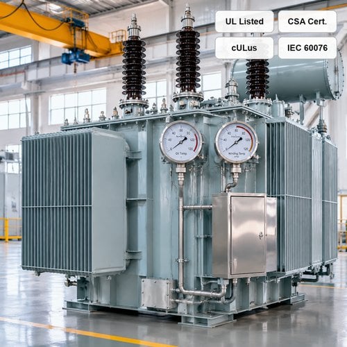
When electrical engineers and procurement managers evaluate distribution and power transformers, the nameplate kVA rating is only the starting point. Operating reliability, total owning cost, and asset longevity are dictated by internal thermal management. Winding conductors and core laminations generate continuous resistive (I²R) and eddy current losses that heat the surrounding dielectric medium. Specifying the correct transformer temperature rise and insulation thermal class determines whether a transformer delivers 30+ years of maintenance-free service or suffers premature dielectric breakdown within its first decade of heavy industrial duty.
Thermal stress is the primary accelerator of electrical insulation degradation. Under the classic Arrhenius chemical reaction rate model—formalized in the electrical power industry as Montsinger's 6°C–10°C half-life rule—operating a transformer continuously just 10°C above its thermal design limit cuts insulation mechanical and dielectric lifespan in half. Conversely, choosing an optimized winding temperature rise rating provides built-in thermal headroom, enabling units to absorb heavy harmonic currents, cyclical overload spikes, and elevated summer ambient temperatures without sacrificing loss-of-life margins.
Fundamental Concepts: Ambient Temperature, Average Winding Rise, and Hot Spot Limits
Transformer temperature ratings are established relative to standardized reference ambients. Both IEEE and IEC standards define reference ambient conditions based on a maximum ambient of 40°C and a 24-hour daily average ambient of 30°C. Total operating temperature at any point inside the transformer is the sum of three distinct components: the ambient temperature, the average temperature rise of the cooling medium/winding, and the localized thermal gradient leading to the hottest spot.
In standard liquid-immersed designs, heat transfers from the copper or aluminum conductors through the cellulose turn insulation into circulating mineral oil or natural ester fluid, which dissipates heat via external radiators. The critical parameter governing insulation aging is the transformer hot spot temperature (θHS), located in the upper third of the winding coils where cooling fluid velocity and convective heat transfer gradients create peak local temperatures. Per IEEE C57.91 Guide for Loading Mineral-Oil-Immersed Transformers, calculating this hot spot requires evaluating the top-oil temperature rise over ambient (ΔθTO) and the winding hot-spot-to-top-oil gradient (ΔθH-TO):
θHS = θA + ΔθTO + ΔθH-TO
Where θA represents the ambient temperature (nominally 30°C daily average), ΔθTO represents the top-oil temperature rise (typically 50°C–55°C at rated load), and ΔθH-TO represents the hot-spot gradient over top-oil (typically 15°C in standard ONAN cooling designs). For standard 65°C average winding rise units, the maximum continuous hot-spot temperature at rated nameplate load in a 30°C average ambient is exactly 110°C (30°C + 65°C + 15°C = 110°C).
Liquid-Immersed Transformers: 55°C Rise vs 65°C Rise and 55/65°C Dual Ratings
In North American utility and industrial distribution networks governed by IEEE C57.12.00 Standard General Requirements for Liquid-Immersed Transformers, buyers routinely encounter two standard winding rise classifications: 55°C rise and 65°C rise. Understanding the metallurgical and chemical differences between these two specifications is critical for proper asset sizing:
1. Standard 55°C Rise (Class 105 Insulation System): Historically built using non-upgraded kraft paper insulation with a thermal index of 105°C. In a 30°C average ambient, a 55°C average winding rise yields a maximum hot-spot temperature of 95°C (30°C ambient + 55°C average rise + 10°C gradient), corresponding to normal life expectancy benchmarked at 20.55 years (180,000 hours).
2. Standard 65°C Rise (Class 120 Thermally Upgraded Kraft Insulation): Modern transformers utilize Thermally Upgraded Kraft (TUK) paper treated with nitrogenous agents (dicyandiamide, melamine, or polyacrylamide) that inhibit acid-catalyzed hydrolysis of cellulose chains. TUK paper elevates the thermal endurance limit to 120°C. In a 30°C average ambient, a 65°C average winding rise produces a continuous hot-spot temperature of 110°C, delivering the exact same 20.55-year normal life expectancy despite operating 15°C hotter.
3. The 55°C/65°C Dual Rating Advantage: When a transformer is engineered with a 65°C-capable TUK insulation system but sized with sufficient core cross-section, copper conductor area, and radiator cooling surface to limit its baseline temperature rise to 55°C at nameplate kVA, it gains a dual rating (e.g., 1000/1120 kVA or 2500/2800 kVA). Operating at the higher 65°C rise rating provides an immediate +12% continuous overload capacity without forced cooling fans (ONAN) and without sacrificing insulation life.
When evaluating liquid immersed transformer temperature rise, industrial facility designers often specify 55°C rise units even when 65°C insulation is installed. This conservative design choice drastically lowers winding resistance, reducing continuous I²R load losses and helping facilities comply with stringent US Department of Energy Efficiency Standards across the entire operating lifecycle.
Dry-Type Transformers: 80°C, 115°C, and 150°C Rise Across Thermal Classes
For indoor substations, commercial buildings, data centers, and industrial plants where fire safety precludes mineral oil, dry-type transformers (both Vacuum Pressure Impregnated [VPI] and Cast Resin [CRT]) are the dominant choice. Unlike liquid-filled units, dry-type insulation systems rely on solid dielectric barriers (aromatic polyamide Nomex paper, fiberglass, and epoxy resins) cooled by natural air convection (AN) or forced draft fans (AF).
Standard dry type transformer temperature rise specifications under IEEE C57.12.01 and IEC 60076-11 are categorized by their allowable temperature rise over a 30°C average (40°C maximum) ambient:
• Class 150°C Rise (Class 220 Insulation / Class H/R): The conventional commercial standard. Utilizes 220°C rated insulation materials with an allowable 150°C average winding rise and a 30°C hot-spot allowance, resulting in a maximum operating hot spot of 220°C (40°C max ambient + 150°C rise + 30°C hot spot = 220°C). While offering the lowest initial capital cost and most compact footprint, full-load operating losses and enclosure heat rejection are highest.
• Class 115°C Rise (Class 220 Insulation): Uses the same 220°C high-temperature insulation system but increases conductor cross-sectional area and cooling airflow to restrict average winding rise to 115°C. In a 40°C ambient, maximum hot-spot temperature reaches 185°C—leaving a 35°C safety margin below the insulation material's thermal rating. This enables approximately 15% continuous overload capability above nameplate.
• Class 80°C Rise (Class 220 Insulation): The premium industrial and mission-critical data center specification. By engineering heavy conductor cross-sections with low current density and generous internal cooling ducts, winding rise is held to just 80°C. Operating with a maximum hot-spot of 150°C against a 220°C insulation capability provides an extraordinary 70°C thermal margin. An 80°C rise dry-type transformer can deliver up to +30% continuous overload capacity indefinitely without forced cooling fans and operates with 20% to 35% lower load losses compared to a standard 150°C rise unit.
Engineering Comparison: Temperature Rise and Insulation Class Matrix
The following technical matrix compares standard liquid-immersed and dry-type transformer temperature rise ratings, insulation thermal indices, and operational characteristics:
| Transformer Type & Technology | Insulation Thermal Class | Rated Average Winding Rise | Max Hot Spot Temp @ 40°C Amb | Reserve Overload Margin (Self-Cooled) | Relative Load Loss (I²R) |
|---|---|---|---|---|---|
| Liquid-Filled (Standard Kraft) | Class 105 (A) | 55°C | 105°C | Baseline (0%) | Low |
| Liquid-Filled (TUK Paper) | Class 120 (E) | 65°C | 120°C | Baseline (0%) | Standard |
| Liquid-Filled (55/65°C Dual) | Class 120 (E) | 55°C @ Base / 65°C @ Peak | 105°C Base / 120°C Peak | +12% continuous at 65°C | Lowest among liquid units |
| Dry-Type (Standard Commercial) | Class 220 (H / R) | 150°C | 220°C | Baseline (0%) | Highest |
| Dry-Type (Intermediate Efficiency) | Class 220 (H / R) | 115°C | 185°C | +15% continuous | Moderate (10-15% lower) |
| Dry-Type (Premium Low-Loss / Data Center) | Class 220 (H / R) | 80°C | 150°C | +30% continuous | Lowest (25-35% lower) |
Real-World Engineering Challenges: High Ambient, Altitude, and Non-Sinusoidal Harmonics
In real-world field installations, operating conditions rarely mirror benign laboratory nameplate standards. Electrical specifiers must account for three critical environmental and operational derating factors during winding rise sizing:
1. Elevated Ambient Temperatures: If a transformer operates in desert environments (such as Texas, Arizona, or the Middle East) where summer peak ambient temperatures reach 50°C (exceeding the standard 40°C maximum), the transformer will overheat at nameplate loading. For every 1°C increase in ambient above 40°C, the allowable load must be derated by approximately 1.0% to 1.5% for liquid-immersed units and 1.2% to 2.0% for dry-type units unless the unit is custom-engineered with a reduced temperature rise (e.g. specifying a 45°C rise oil-immersed unit or an 80°C rise dry-type unit for 50°C ambient service).
2. High Altitude Derating (>1,000 m / 3,300 ft): In high-altitude installations (mining projects in Colorado, Chile, or high plateaus), the lower density of ambient air reduces convective heat transfer efficiency across radiator fins and dry-type coil surfaces. Per IEEE C57.12.00, for liquid-immersed self-cooled (ONAN) transformers operating above 1,000 meters, average winding temperature rise increases by 0.4% for every 100 meters above 1,000 m. For dry-type self-cooled (AN) units, winding rise increases by 0.5% per 100 meters. Specifying an oversized core/coil assembly or lower nominal rise ensures reliable operation without thermal trips at elevation.
3. Non-Linear Loads and Harmonic K-Factor Heating: Power electronics, variable frequency drives (VFDs), EV fast charging hubs, and solar/battery inverters inject non-sinusoidal harmonic load currents into transformer windings. Harmonic eddy current losses increase proportionally to the square of harmonic frequency (PEC ∝ ∑ Ih² · h²). A standard 65°C rise transformer loaded to 100% kVA under a K-13 harmonic profile will experience local hot-spot temperatures exceeding 140°C, rapidly aging the paper insulation. Sizing K-factor rated transformers with electrostatic shielding and lower baseline winding rise prevents localized thermal runaway.
Factory Acceptance Testing: How Temperature Rise Is Verified
In our 120,000 m² manufacturing plant equipped with 180+ sets of precision fabrication and testing equipment, temperature rise verification (heat run testing) is performed in strict compliance with IEEE C57.12.90 and IEC 60076-2 protocols. As an authorized Eaton joint venture manufacturing partner, Ryan Electric implements rigorous thermal validation procedures on every prototype and custom-engineered power unit.
The temperature rise test utilizes the short-circuit method. Total losses (no-load core losses plus rated load losses corrected to reference temperature) are injected into the transformer windings until top-oil temperature rise and tank cooling rates stabilize (defined as a rate of change less than 1°C per hour over three consecutive hours). Once thermal equilibrium is reached, rated current is applied for one hour to establish accurate winding-to-oil thermal gradients.
At the instant of power shutdown, precision Kelvin four-wire micro-ohmmeters capture winding DC resistance decay curves over a 15-minute cooling interval. The resistance curve is extrapolated back to the exact instant of shutdown (t=0) to calculate average hot winding resistance (Rhot). The average winding temperature rise (ΔTwdg) is determined using the fundamental copper resistance-temperature formula:
ΔTwdg = [(Rhot - Rcold) / Rcold] · (234.5 + Tcold) + Tcold - Tambient
Fiber-optic temperature probes embedded directly into high-voltage winding turn ducts during coil winding allow our testing engineers to map real-time internal hot spots, confirming that hot-spot gradient allowances never exceed IEEE C57.12.00 design limits.
Procurement and Sizing Recommendations for EPCs and Facility Managers
When preparing equipment specifications for pad-mounted distribution transformers, substation power transformers, or indoor dry-type units, applying the following engineering guidelines ensures optimal balance between initial capital expense and long-term asset reliability:
• For Commercial & Light Industrial Dry-Type Applications: If ambient temperatures are controlled (indoor HVAC) and continuous load factors average below 60%, a standard 115°C or 150°C rise Class 220 dry-type unit offers an economical, fire-safe solution.
• For Data Centers, Semiconductor Fabs, and Heavy Industrial Process Plants: Always specify an 80°C rise dry-type transformer with Class 220 insulation. The lower I²R losses reduce 24/7 HVAC cooling load in the electrical room, and the 30% reserve continuous overload capacity provides vital resilience during UPS battery recharge cycles and utility switching transients.
• For Outdoor Pad-Mounted & Substation Transformers: Require a 55°C/65°C dual rating with Thermally Upgraded Kraft paper and mineral oil or ester fluid. The 55°C rating provides superior baseline energy efficiency under standard loading, while the 65°C rating unlocks immediate 112% continuous peak load capacity without requiring auxiliary fan power.
• For Renewable Solar/BESS Inverter Duty: Specify 65°C rise oil-immersed or 80°C/115°C rise cast resin transformers engineered for high ambient (50°C ambient reference) with K-4 or K-9 harmonic withstand ratings to counter high-frequency PWM switching harmonics.
About the Author
Ryan Electric Engineering Team — Specialists in medium-voltage and high-voltage transformer design, manufacturing custom oil-immersed, pad-mounted, and dry-type transformers certified to UL, CSA, IEEE, and IEC standards from our state-of-the-art 120,000 m² facility. For custom temperature rise sizing, thermal loss evaluations, or quotation requests, contact our technical applications team at [email protected].
Table of Contents
- Fundamental Concepts: Ambient Temperature, Average Winding Rise, and Hot Spot Limits
- Liquid-Immersed Transformers: 55°C Rise vs 65°C Rise and 55/65°C Dual Ratings
- Dry-Type Transformers: 80°C, 115°C, and 150°C Rise Across Thermal Classes
- Engineering Comparison: Temperature Rise and Insulation Class Matrix
- Real-World Engineering Challenges: High Ambient, Altitude, and Non-Sinusoidal Harmonics
- Factory Acceptance Testing: How Temperature Rise Is Verified
- Procurement and Sizing Recommendations for EPCs and Facility Managers
- About the Author