
 EN
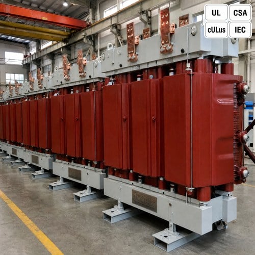
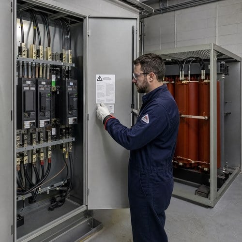
The label on the switchboard said 8 cal/cm2. The study behind it had been run against a 1,500 kVA transformer at 5.75% impedance, a unit that was pulled out eighteen months earlier and replaced with a 2,000 kVA unit carrying the same nameplate impedance. Nobody re-ran the study. Nobody reprinted the label. The electrician who opened the section that morning was dressed for the number on the sticker, and the incident energy at that point was closer to 20 cal/cm2.
We build transformers, and this is the part of arc flash work that falls between the electrical contractor and the manufacturer: the transformer is the source of the fault current, so anything that changes the source changes the hazard. A specification that lists kVA, voltage and impedance but stops there leaves the study team guessing at tolerance, clearing time and winding configuration. Here is what each of those does to incident energy, and what to put in writing before the study starts.
How the Transformer Sets the Available Fault Current
Bolted fault current at the secondary terminals comes from one relationship: secondary full-load current divided by percent impedance. Take a three phase transformer rated 2,000 kVA, 13.8 kV delta to 480Y/277 V. Secondary full-load current is 2,406 A. At 5.75% transformer impedance, the bolted fault current is 2,406 / 0.0575 = 41.8 kA, ignoring the impedance of the upstream source and the service conductors.
Real numbers land lower. A 2,000 kVA unit fed from a utility with 150 MVA of available short-circuit capacity will typically deliver 30 kA to 35 kA at the secondary terminals rather than 41.8 kA. The transformer still dominates the calculation. Raise the impedance to 7.5%, which many utilities specify to hold fault current down and protect their own equipment, and the bolted value drops to 32.1 kA. Same kVA, same voltages, 23% less fault current, and a different study with a different label.
That spread bites at the equipment level before anyone talks about PPE. A switchboard with a 22 kA interrupting rating is ordinary in light industrial work. Put a low-impedance 2,000 kVA unit in front of it and the available fault current exceeds the rating of the gear unless a series-rated combination or a higher AIC assembly is used. We see this argument on drawings most months: the utility wants higher impedance, the facility wants better voltage regulation, and the gear was purchased before either conversation happened.
Winding configuration sets the other half of the fault current picture. A delta-wye unit gives a low-impedance path for single-line-to-ground faults on the secondary, and that current is often 50% to 60% of the three-phase bolted value. A delta-delta unit has no return path for ground current on the secondary, so a ground fault behaves very differently. The vector group on the nameplate is not a drawing detail. It decides which fault the study engineer has to calculate.
The Three Variables That Move Incident Energy
An incident energy value is a function of how much current flows during the arc, how long the arc lasts, and how far the worker stands from it. The transformer controls the first. The overcurrent device and its settings control the second. The equipment layout controls the third. A study that fixes only one of the three is not a study, it is an estimate with a cover page.
| Variable | What moves it | Effect on incident energy | Where the transformer fits |
| Available fault current | Transformer kVA and %Z, plus utility source strength and conductor length | Rises with arcing current, and rises faster once the arc stabilises at high current | 2,000 kVA at 5.75% gives about 41.8 kA bolted at 480 V |
| Clearing time | Device type, settings, coordination, maintenance-mode settings | Nearly linear: halving the time roughly halves the energy | Larger units push upstream devices onto slower curves |
| Working distance | Enclosure depth, barriers, task position | Falls off steeply as distance grows | Terminations sit deeper inside larger enclosures |
The clothing tables in NFPA 70E step at 4, 8, 12, 25 and 40 cal/cm2, and the 2027 edition is the one now in force for most U.S. sites. The jump from a 4 cal/cm2 boundary to an 8 cal/cm2 boundary is the difference between daily-wear arc-rated clothing and a full suit with a hood, and in a lot of plants that difference decides whether a task is done in-house or contracted out. Above 40 cal/cm2, most operators stop treating energized work as an option at all.
The reason to design around that ceiling is that it is rarely the arc current that pushes a section over the line. It is almost always the clearing time. Two facilities with identical 2,000 kVA services can sit on opposite sides of the 40 cal/cm2 line purely because one upstream breaker has a 0.4 s trip and the other has a current-limiting fuse.
Where Impedance Tolerance Quietly Changes the Number
A nameplate impedance is a declared value, not a measured one. IEEE C57.12.00 allows the measured impedance of a two-winding transformer to differ from the declared value by plus or minus 7.5% of that value. On a unit declared at 5.75%, the routine test can land anywhere from 5.32% to 6.18% and still be a conforming transformer. Translated into fault current at 480 V, that is 45.2 kA on one end and 38.9 kA on the other.
Neither number is wrong. The problem is that a study run at 5.75% is describing a transformer impedance that may never have been built. When we issue a routine test report under IEEE C57.12.90, the impedance measured at rated current is on the page. Hand that measured value to the study engineer and the calculation stops moving. When a customer wants a tight window, we can usually hold it by adjusting winding geometry and core window height, but it costs copper and it costs weeks, and that is worth knowing before the purchase order rather than after.
There is a second-order effect that surprises people. Lower impedance also means higher mechanical forces on the windings during a fault and higher through-fault current on the upstream device. A unit built to 5.4% instead of 5.75% is not simply a more efficient unit, it is a unit with a different short-circuit duty, and IEC 60076-5 is where the demonstration of that duty lives.
Clearing Time Is the Lever Most Projects Ignore
Incident energy tracks arcing time almost linearly. A fault cleared in 0.1 s by a current-limiting fuse deposits roughly one fifth of the energy of the same fault held for 0.5 s by a thermal-magnetic breaker on its long-time curve. Same transformer, same 41.8 kA available, same person in the same spot: one task calls for an 8 cal/cm2 kit, the other calls for a suit nobody wants to wear in July.
This is why the coordination study and the arc flash study have to be read by the same people. A breaker set high enough to ride through the next transformer's inrush can push feeder clearing time past a full second. A ground fault relay set at 1,200 A on a 480 V system with a 2,000 kVA source may never see a low-level arcing fault at all, and the fault burns until something else clears it. Maintenance-mode switches and zone-selective interlocking exist to buy that time back, and they help only if the settings are documented and the label reflects them.
Labels age in both directions. A transformer upgrade raises the current; a relay replacement or a coordination tweak can lower the time. We have walked into plants where the study was five years old, the service had doubled, and the sticker on the gear still carried the original number. NEC 110.16 requires the label to be there. OSHA 1910.269 and the general industry electrical rules assume a hazard analysis sits behind every PPE choice, and nothing in the code requires anyone to notice when the sticker becomes untrue.
What We Do When a Customer Specifies an Impedance Window
Our design review starts with the fault current the customer's gear can actually withstand, not with a preferred percentage. If the switchgear is rated 22 kA and the site needs 2,000 kVA, we will normally propose a unit in the 6.5% to 7% range and accept a small regulation penalty, or split the load across two services so each transformer feeds gear rated for its own fault level. Both options are cheaper than replacing a switchboard that was specified before the transformer.
Since 2023 Ryan Electric has operated as an Eaton joint-venture partner, and the drawing discipline that came with that work is why we push back when a specification lists an impedance with no tolerance and no measured test value attached.
We also hand over the routine test pages with every unit: ratio, winding resistance, impedance, no-load loss, load loss, and the temperature rise figures from the heat run. Those are the inputs an arc flash study needs, and they are more useful than a catalogue impedance curve. Dry type units for North American projects leave the plant UL listed or cULus marked depending on the category, and Canadian orders carry CSA marking. The standard behind the marking changes the design margins, and it changes what the nameplate is allowed to claim.
There is a schedule argument too. If a study comes back after the transformer is built and the answer is that the impedance has to change, the unit is scrap and the project restarts in a queue that runs past a year for medium voltage classes. Twenty minutes of review at quotation stage is the cheap version of that conversation.
A Pre-Study Checklist for the Transformer Specification
Give the study engineer these items and the calculation stops being a negotiation.
| Spec item | What to write | Why the study needs it |
| Primary and secondary voltage | System nominal plus tap range | Sets base current on both sides |
| kVA | Maximum demand with planned growth, not nameplate habit | Sets the fault current magnitude |
| Impedance | Nominal %Z plus the acceptable tolerance window | Gives a fault current range instead of one number |
| Winding configuration | Delta-wye or delta-delta, and the vector group | Determines ground fault current and its path |
| Test report | Measured %Z at rated current from routine tests | Replaces the design value with a real one |
| Overcurrent device | Type, frame, rating, settings and expected clearing time | Multiplies directly into incident energy |
| Label | NEC 110.16 label showing study results and PPE boundary | What the electrician in the field actually reads |
Two rows deserve an argument in the design meeting: the impedance window and the clearing time. Everything else is a fact you either have or can obtain from the utility. The two that get skipped are the two that move the number.
Where This Leaves Your Specification
An arc flash label is a snapshot of three things: a transformer, a breaker setting and a working distance. Change any one of them and the sticker is out of date. The cheapest way to keep it current is to specify a unit whose fault contribution you can predict, with measured impedance on the test report, a documented tolerance, and a winding configuration the study engineer asked for rather than assumed.
If you are sizing a transformer for a project that will carry an arc flash study, send us the secondary voltage, the kVA, the rating of the gear downstream and the impedance your utility prefers. We will come back with a proposal that states the fault current range and the test values behind it, not just a nameplate percentage. Reach the engineering team through the contact page, or browse three phase pad mounted transformers and dry type transformers for the classes we build up to 44 kV and 10,000 kVA.
About the Author
This article was prepared by the Application Engineering Team at Ryan Electric (Jiangsu Ryan Electric Co., Ltd.), a transformer manufacturer in China supplying oil immersed, dry type and pad mounted transformers to North America, the Middle East, Southeast Asia and Africa since 2007. The team reviews impedance, short-circuit duty and protection coordination questions on custom three phase units, and prepares routine and type test documentation, and UL / cULus / CSA / IEEE / IEC certification packages for utility, data center and industrial projects. Drawing reviews and specification questions can be sent through the contact form at www.ryantransformers.com. Last reviewed: October 2026.
Disclosure: Ryan Electric manufactures and sells the transformers discussed in this article. Code and standard references (NEC 110.16, IEEE C57.12.00, IEEE C57.12.90, IEEE 1584, NFPA 70E, IEC 60076-5) are summarised for engineering discussion only. Arc flash incident energy values must come from a study performed for the specific installation by a qualified engineer.
Table of Contents
- How the Transformer Sets the Available Fault Current
- The Three Variables That Move Incident Energy
- Where Impedance Tolerance Quietly Changes the Number
- Clearing Time Is the Lever Most Projects Ignore
- What We Do When a Customer Specifies an Impedance Window
- A Pre-Study Checklist for the Transformer Specification
- Where This Leaves Your Specification