
 EN
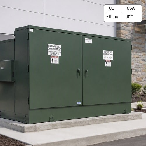
When specifying medium-voltage distribution equipment for commercial developments, renewable energy sites, or utility grids, one of the most critical decisions confronting electrical engineers is the selection between dead front and live front compartment architectures. As a premier pad mounted transformer manufacturer, Ryan Electric routinely guides project engineers through the trade-offs that govern high-voltage terminations, operator safety clearances, switching maintenance, and life-cycle costs. Making the wrong choice can lead to failed utility inspections, severe arc-flash liabilities, or unnecessary retrofit expenses down the road.
Why Compartment Front Design Dictates Distribution Safety and Reliability
In underground medium-voltage distribution networks (typically operating between 2.4 kV and 34.5 kV), the pad-mounted transformer serves as the vital link stepping down utility feeder voltages to usable 480V/277V or 208V/120V service. However, because these units are placed at grade level in publicly accessible outdoor areas—such as shopping center parking lots, school campuses, and residential subdivisions—the high-voltage (HV) terminal compartment must provide an impenetrable barrier against unauthorized contact.
The fundamental distinction between a dead front pad mounted transformer and a live front pad mounted transformer lies in whether energized electrical conductors and terminations remain exposed when the high-voltage cabinet doors are opened by authorized utility personnel. In a live-front configuration, incoming medium-voltage cables terminate directly onto exposed porcelain or epoxy bushings, presenting bare, energized metal parts inside the compartment. Conversely, a dead-front design encloses all high-voltage connections within fully shielded, insulated, and grounded separable rubber connector assemblies.
Construction Architecture: Bushing Wells vs Exposed Porcelain Bushings
The physical layout of the high-voltage compartment reflects distinct manufacturing philosophies and operating standards:
1. High-Voltage Bushings and Terminations: In a dead-front transformer, the tank wall is equipped with welded bushing wells or integral 600A deadbreak bushings complying with IEEE Std 386. For 200A loadbreak applications (common up to 25 kV or 35 kV systems), replaceable bushing well inserts mate with elbow connectors made of peroxide-cured EPDM rubber. The outer conductive jacket of the elbow is bonded directly to the transformer tank ground, ensuring that the external surface remains at zero electrical potential. In contrast, live-front units utilize traditional porcelain bushings with spade or stud terminals, requiring exposed copper crimp lugs and generous physical clearances to prevent phase-to-phase and phase-to-ground flashovers.
2. Compartment Dimensions and Footprint: Because live-front terminations require mandatory air strike and creepage distances (often exceeding 8 to 12 inches between live phases at 15 kV), the high-voltage cabinet must be significantly deeper. Dead-front designs, benefiting from solid dielectric insulation, allow compact phase-to-phase spacing, reducing total cabinet depth and overall pad footprint.
3. Wildlife and Environmental Ingress Protection: In outdoor installations, moisture condensation, insects, and small rodents pose severe operational hazards. In our testing bays and field audits, Ryan Electric engineers frequently observe that live-front units in coastal or agricultural regions suffer flashovers caused by animal intrusion across exposed terminals. A dead-front arrangement eliminates this vulnerability because no energized surface is exposed to the surrounding ambient air.
Safety Standards and Operational Protocols: IEEE C57.12.28 and OSHA Compliance
Enclosure integrity and operational safety are strictly regulated by North American standards. Under IEEE C57.12.28, pad-mounted equipment must pass stringent tamper-resistance evaluations, including pry-bar tests, hinge pull tests, and 1,000-hour salt spray corrosion testing to protect the general public. Furthermore, personnel safety during routine operation is governed by OSHA 1910.269 Electric Power Standards (29 CFR 1910.269), which mandates strict minimum approach distances and personal protective equipment (PPE) requirements when working near energized parts.
When lineworkers service a live-front transformer, the entire high-voltage compartment is classified as an exposed shock and arc-flash hazard zone. Technicians must wear high-category arc-flash suits, use voltage detectors, and install insulating rubber blankets before approaching adjacent phases. Conversely, operating a dead front pad mounted transformer allows trained crews to perform switching operations—such as disconnecting a 200A loadbreak elbow under energized conditions using an insulated hot stick—while maintaining a shielded ground plane between themselves and the medium-voltage conductor.
In our manufacturing process as a dedicated pad mounted transformer manufacturer, Ryan Electric rigorously enforces both IEEE C57.12.28 and CSA C22.2 standards, ensuring that all cabinet doors, penta-head security bolts, and padlock provisions exceed utility tamper-resistance mandates.
Technical Comparison: Dead Front vs Live Front Specifications
To assist procurement teams and consulting engineers in evaluating their technical specifications, the following comparison matrix highlights the key engineering parameters:
| Engineering Parameter | Dead Front Configuration | Live Front Configuration |
|---|---|---|
| High-Voltage Termination Type | Separable insulated elbow connectors (IEEE Std 386) on bushing wells/inserts | Exposed porcelain bushings with stud or NEMA 2-hole/4-hole spade terminals |
| Operator Shock Hazard | Zero exposed energized parts; shielded outer conductive jacket bonded to ground | High; exposed energized conductors present when HV door is opened |
| Switching Capability | Loadbreak elbows allow energized hot-stick switching up to 200A / 25 kV | Requires internal oil-immersed loadbreak switch or upstream de-energization |
| Cabinet Space & Footprint | Compact cabinet depth; minimal phase-to-phase air clearance required | Deeper cabinet required to maintain mandatory phase strike/creepage distance |
| Wildlife / Moisture Immunity | Immune to animal bridging and dust/moisture contamination | Vulnerable to animal intrusion and surface tracking on porcelain |
| Primary Voltage Range | 2.4 kV through 34.5 kV (95 kV to 150 kV BIL) | 2.4 kV through 34.5 kV (legacy industrial & utility retrofit) |
| Typical Applications | North American utilities, schools, retail centers, solar/BESS sites | Industrial substations, fenced utility yards, legacy infrastructure |
Switching Flexibility, Fusing, and Surge Protection Integration
Beyond basic terminations, the choice between dead front and live front fundamentally impacts protection and sectionalizing flexibility:
1. Loop Feed vs. Radial Feed Switching: Modern underground distribution networks overwhelmingly utilize loop-feed designs to facilitate circuit reconfiguration without customer outages. In a dead-front loop-feed transformer, six HV bushing wells (two per phase: A1/A2, B1/B2, C1/C2) permit incoming and outgoing feed-through loops. Lineworkers can quickly isolate a faulted cable section by moving an elbow connector to an adjacent insulated standoff parking bushing with a standard hot stick.
2. Fusing Co-ordination: Both dead-front and live-front units can be equipped with Bay-O-Net draw-out expulsion fuses in series with internal partial-range current-limiting back-up fuses (ELSP). In dead-front units, the Bay-O-Net fuse holders are positioned above the insulated elbows, allowing hot-stick fuse replacement without draining dielectric fluid or opening the main tank seal.
3. Elbow Surge Arresters: In dead-front installations, medium-voltage metal oxide varistor (MOV) surge arresters are integrated directly into the elbow interface (elbow arresters), mounting onto bushing inserts or feed-through devices. This creates a compact, fully shielded overvoltage protection scheme that complies with U.S. Department of Energy (DOE) Distribution Transformer Standards and IEEE insulation coordination principles.
How Ryan Electric Engineers Custom Pad-Mounted Units for Global Projects
As an established pad mounted transformer manufacturer operating from a 120,000 square meter modern manufacturing facility with over 37 patents, Ryan Electric delivers precision-engineered liquid-immersed transformers tailored to North American, Latin American, and international utility standards. Since 2023, our official joint venture partnership with Eaton has further expanded our engineering capabilities and quality assurance protocols.
Our three-phase and single-phase pad-mounted transformers (rated from 45 kVA up to 10,000 kVA, primary voltages up to 35 kV with BIL up to 150 kV) offer versatile configuration options:
• Certified Compliance: Fully compliant with IEEE C57.12.00, IEEE C57.12.28, IEEE C57.12.34, UL, and CSA standards, certified by third-party testing bodies including DEKRA and CNAS.
• Advanced Dielectric Fluids: Available with high-grade inhibited mineral oil (meeting ASTM D3487) or eco-friendly, high-fire-point natural ester fluid (FR3) providing enhanced thermal headroom and 65°C average winding temperature rise.
• Robust Corrosion Protection: Multi-stage powder-coat finish exceeding 1,000-hour salt spray testing under IEEE C57.12.28, with optional 304L or 316L stainless steel tanks and sills for harsh coastal and industrial environments.
• Custom Compartment Outfitting: Engineered with 200A loadbreak wells or 600A/900A deadbreak bushings, internal four-position T-blade or two-position on/off loadbreak switches, and customized LV spade configurations up to 16 holes per terminal for heavy multi-cable runs.
Practical Utility and Commercial Selection Decision Matrix
To determine whether your facility or grid project should specify dead front or live front construction, review the following field-proven guidelines:
• Specify Dead Front When: The transformer is installed in public or semi-public areas (commercial plazas, universities, parks); the local electric utility mandates separable insulated connectors; hot-stick loadbreak switching without external disconnects is required; or maximum personnel safety and minimized arc-flash boundaries are top priorities.
• Specify Live Front When: The transformer is located inside a locked, perimeter-fenced utility substation with restricted access; direct mechanical bolting of oversized medium-voltage conductors is necessary; or you are replacing an existing live-front unit on a pre-cast concrete pad where existing cable training geometry prevents elbow radius bending.
Conclusion and Actionable Procurement Steps
While live-front transformers have historically served industrial and fenced substation environments, the modern utility and commercial standard across North America has decisively shifted toward dead-front pad-mounted designs. By enclosing energized components within grounded, touch-safe elbow systems, dead-front units dramatically improve worker safety, prevent costly animal-related outages, and streamline grid maintenance.
When preparing your next medium-voltage submittal or distribution upgrade, partnering with an experienced pad mounted transformer manufacturer ensures that every detail—from bushing height clearances to short-circuit withstand capabilities—satisfies both local utility interconnections and national safety codes. Contact the Ryan Electric technical team today to review your project drawings or request a customized engineering quotation.
About the Author: Ryan Electric Engineering Technical Team specializes in the design, testing, and manufacturing of IEEE, UL, and CSA certified liquid-immersed and dry-type distribution transformers for utility, commercial, and renewable energy infrastructure worldwide.
Table of Contents
- Why Compartment Front Design Dictates Distribution Safety and Reliability
- Construction Architecture: Bushing Wells vs Exposed Porcelain Bushings
- Safety Standards and Operational Protocols: IEEE C57.12.28 and OSHA Compliance
- Technical Comparison: Dead Front vs Live Front Specifications
- Switching Flexibility, Fusing, and Surge Protection Integration
- How Ryan Electric Engineers Custom Pad-Mounted Units for Global Projects
- Practical Utility and Commercial Selection Decision Matrix
- Conclusion and Actionable Procurement Steps