
 EN
Last November a 2,000 kVA cast-resin unit was set on its pad outside Johor Bahru with a complete document package — UL label, CSA mark, routine test report, winding resistance figures. Ninety minutes after the contractor closed the main breaker it was offline again. One secondary phase had been landed on the wrong bus, and nobody had checked rotation before energizing. The transformer was fine. The transformer commissioning was not.
A factory test report answers exactly one question: did this unit meet nameplate on the day it was tested, at 20 °C, in a controlled test bay, with calibrated instruments. It says nothing about the six weeks between that test and your first close — the flat rack, the ocean freight, the crane lift, the electrician who wired the control panel without the drawing. Transformer commissioning is the process that closes that gap, and on a late project it is always the first step somebody offers to shorten.
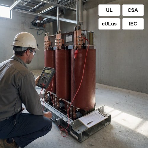
Factory Tests Are Not Field Acceptance
Every unit we build leaves the works with routine tests to IEEE C57.12.90-2021: winding resistance, ratio on every tap, no-load loss and excitation current, impedance and load loss, applied and induced potential, and a partial discharge check on medium-voltage windings. Those numbers become the baseline you compare against for the next twenty years, so keep the report somewhere you can still find it in 2045.
The field side runs on a different standard, and it is not the factory one. ANSI/NETA ATS exists to establish "suitability for initial energization" — that is the exact wording on the ANSI/NETA ATS-2025 page — and it assumes a unit that has been shipped, stored and wired by other people. A passing factory report is the reason to run field tests. It is not a replacement for them.
Checks 1 to 4: Paper, Nameplate and the Mechanical Walk-Down
Start with paper, because paper finds half the failures before anyone opens a panel.
- Nameplate against submittal. kVA, primary and secondary voltage, vector group, impedance, tap range, temperature rise, insulation class. Dyn11 is not Dyn1: a vector group copied wrong from the drawing will parallel happily and then trip the moment load balances.
- Certification marks on the plate itself. North American inspectors look for the UL or cUL mark and, in Canada, the CSA mark, physically on the nameplate rather than in a folder. Dry-type distribution units from 601 V to 35 kV fall under UL 1562, including cast and resin-encapsulated designs.
- Shock, tilt and humidity indicators. A tripped gauge means internal inspection before acceptance. On cast-resin units also check the coil ends for whitening or hairline cracks — that is impact damage, not cosmetic.
- Torque, enclosure and clearances. Busbar and lug torque per the manufacturer's table rather than by feel. NEMA 3R outdoors, NEMA 1 indoors. Working clearances per drawing, and a grounding electrode conductor sized for a separately derived system.
We photograph all four at delivery. It takes twenty minutes and has settled two freight claims in three years.
Checks 5 to 8: The Four Electrical Tests That Earn Their Time
Four field tests carry most of the weight in a transformer commissioning program. Run them in this order and write every reading down, because the numbers only become useful when someone can compare them later.
Insulation resistance comes first, measured on each winding to ground and to the other winding: 500 V DC for LV windings, 1,000 to 2,500 V DC for medium voltage, read at one minute and again at ten. The polarization index is the ten-minute value divided by the one-minute value, and it tells you more than the absolute megohms, because it shows whether moisture is still migrating through the insulation. Below 2.0 on a new oil-filled unit we stop and investigate. Correct every reading to 20 °C before comparing it with the factory sheet.
Then ratio, resistance and impedance, in that order.
Ratio on every tap, not just the nominal one. The working tolerance is ±0.5% of nameplate, and a single tap that misses while all the others pass is almost always a tap changer one position off — cheap now, expensive after the load is on. Phase-to-phase winding resistance within 2% on the same tap catches the loose lug or cold joint that no ratio test will ever see. Measured impedance should land within ±7.5% of the guaranteed value for a two-winding unit; if it does not, your coordination study and your voltage-drop numbers are both wrong before the first amp of load arrives.
| Field test | Reference | Accept on a new unit |
|---|---|---|
| Insulation resistance / PI | IEEE C57.12.90 | PI ≥ 2.0, corrected to 20 °C |
| Turns ratio, every tap | IEEE C57.12.90 | within ±0.5% of nameplate |
| Winding resistance balance | Factory test report | ≤ 2% phase to phase, same tap |
| Impedance | IEEE C57.12.00 | within ±7.5% of guaranteed |
| Dielectric withstand | UL 1562 | 2 × rated + 1,000 V, LV windings |
If the unit is medium voltage, take an SFRA fingerprint before energization. Twenty minutes of sweep buys the only honest baseline you will ever own; without it, a comparison in year three has nothing to compare against.
Checks 9 to 12: Protection Settings, Grounding and Tap Position
This is where transformer commissioning goes quiet and wrong, and it is the half of a pre-energization checklist that electricians skip when the schedule slips. Overcurrent protection has to satisfy two documents at once — NEC 450.3 sets the ceiling, the coordination study sets the installed value — so check the fuse or breaker against both. Then confirm the tap position. Units ship on the mid tap; moving it because the supply runs 3% high is a decision worth writing down, not a habit.
Prove every alarm and trip by simulation rather than by inspection: winding and oil temperature alarms, fan and thermostat controls, and on oil units the Buchholz and pressure-relief contacts. A trip circuit nobody tested is wiring, not protection.
Last, phase rotation at the secondary, then again at the first downstream panel. That is the Johor failure, and it costs one rotation meter and two minutes.
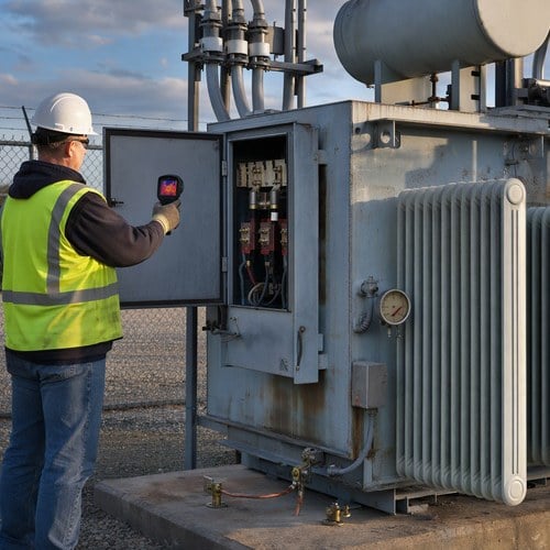
Thermal scan of LV terminations on an oil-immersed distribution transformer before load is applied.
First Energization: The First Sixty Minutes
Energize unloaded. Inrush will pull four to twelve times rated current for a handful of cycles — expected, not a fault. A breaker that trips on the first close deserves investigation before a second close, because the second attempt starts from a partly magnetized core and can trip harder. Watch no-load current against the factory figure and listen for the sound signature: a steady hum at twice line frequency is normal, a crackle or a beat frequency is not.
Scan terminations and busbar joints with a thermal camera inside the first half hour, and record ambient temperature, winding or oil temperature, and actual voltage at the terminals. Then add load in steps — a quarter, half, full — repeating the scan at each step. Those first images are the reference for every survey that follows, and they cost less than one hour of an electrician's day.
What to Record, and Why It Matters in Year Five
Hand over a commissioning file, not a folder of phone photos: the factory routine test report, field test sheets with instrument serial numbers and calibration dates, as-left protection settings, thermal images annotated with load and ambient, and the SFRA fingerprint. NFPA 70B now treats electrical maintenance as a managed program, and this file is the first element of it. When a dissolved gas sample raises a question in year five, it is the difference between a targeted investigation and replacing a healthy unit.
The stakes are higher on a custom three phase transformer. A catalogue unit has thousands of identical siblings to compare against; a custom unit has one. There is no population data to fall back on, so the day-one baseline is the only reference you will ever own. That is why our field test sheets ship pre-filled — ratio per tap, resistance balance, impedance window, IR minimums — so the electrician compares against real numbers instead of transcribing them from a drawing.
Commissioning Support From the Factory
We build in a 120,000 m² plant with 180+ sets of production equipment, and since 2023 we have operated as an official Eaton joint-venture partner — which means our test sequence and handover documentation follow the format Eaton field engineers expect. On projects with a tight energization window we send the expected field values ahead of the shipment and stay reachable through first energization.
The projects that energize on the first attempt are almost always the ones where the test sheet was filled in before the unit arrived. The ones that do not usually spend a week proving the transformer was never the problem.
If you are drafting a pre-energization checklist for an upcoming project, send us the nameplate and the single-line diagram. We will return the expected field values for your unit — ratio per tap, resistance balance, impedance window, IR minimums — within one working day. Start at our contact page, or ask for the commissioning package that ships with every custom three phase transformer order.
About the Author: This article was written by the engineering team at Ryan Electric (Jiangsu Ryan Electric Co., Ltd.), an Eaton joint-venture partner and UL/CSA-certified transformer manufacturer in Jiangsu, China, supplying dry-type, oil-immersed and pad-mounted transformers to data center, renewable and utility projects in more than 80 countries.
Table of Contents
- Factory Tests Are Not Field Acceptance
- Checks 1 to 4: Paper, Nameplate and the Mechanical Walk-Down
- Checks 5 to 8: The Four Electrical Tests That Earn Their Time
- Checks 9 to 12: Protection Settings, Grounding and Tap Position
- First Energization: The First Sixty Minutes
- What to Record, and Why It Matters in Year Five
- Commissioning Support From the Factory