
 EN
EN
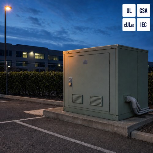
As a pad mounted transformer manufacturer, we keep meeting the same failure in the same order. A pad mounted unit is switched out for maintenance. The riser pole arrester at the end of the cable fails. The crew replaces the arrester, energizes the unit, and the replacement fails again within a few months – sometimes within a few weeks. The transformer itself tests clean on every routine check. Nothing on the nameplate is wrong. What is killing the arrester is ferroresonance, and it is almost never the arrester’s fault.
What Ferroresonance Actually Is
A transformer core is not a linear inductor. Below saturation its magnetizing reactance is high. As the core approaches saturation that reactance collapses. Put a component with that behaviour into a circuit that also contains capacitance — the sheath capacitance of an underground cable, the grading capacitance of a breaker, the capacitance of a bushing or a capacitor bank — and a switching disturbance can drive the circuit into an oscillation that neither element could produce on its own.
That is the whole definition, and it also explains why ferroresonance in transformers is not the tidy resonance you calculate from XL = XC. With a linear inductor there is one resonant frequency and one steady state. With a saturable core there are several, and the circuit can jump between them. IEEE Technology Navigator — Ferroresonance (https://technav.ieee.org/topic/ferroresonance/) describes four principal oscillation modes: fundamental-frequency ferroresonance at the supply frequency; sub-harmonic ferroresonance at a fraction of the supply frequency, most commonly one third; quasi-periodic ferroresonance with irregular waveforms; and chaotic ferroresonance with no repeating pattern at all. Sustained overvoltages in these modes can reach five to six times nominal line voltage, which is far beyond what a distribution winding’s insulation coordination assumes for sustained power-frequency stress.
Two units with identical nameplates can behave completely differently. The mode a circuit settles into depends on inductance, capacitance, voltage magnitude and initial conditions — which in practice means it depends on the exact instant the switch closes. That is why a study built on nominal values will miss it, and why the same switching operation can run clean a hundred times and fail on the hundred and first.
If you are working through a pad mounted specification right now, our engineering team will review the primary circuit with you before the rating is frozen. Send us the one-line diagram and we will walk the four conditions with you.
The Four Conditions That Have to Line Up
Ferroresonance is fussy. It needs four conditions at the same time — an unloaded secondary, high primary capacitance, asymmetrical single-phase switching, and a core that saturates at a modest overvoltage — which is exactly why it never shows up in a load flow study and why it is so hard to reproduce in a test bay.
| Condition | Why it matters | Where it shows up in practice |
| Unloaded or lightly loaded secondary | Load resistance damps the oscillation; an empty secondary provides no damping at all | New subdivision before occupancy, seasonal plant shutdown, unit held as a spare |
| High primary capacitance | Cable sheath capacitance per unit length is far higher than an overhead line | Long underground feeder, riser cable, network vault, cable-fed industrial service |
| Asymmetrical switching | Leaves one or two phases isolated but still capacitively coupled to the source | Single-phase cutouts, one blown fuse, single-pole reclosers, elbow operation |
| Core that saturates at modest overvoltage | Magnetizing inductance collapses, letting the circuit jump between operating points | Modern low-loss cores and designs that run at higher flux density |
Remove any one of the four and the phenomenon usually will not start. That is the useful part, because it means there are four separate places to design it out — and the cheapest is almost always the switching arrangement. It is also the point at which the conversation should move from a quotation to a selection, and it is the first thing a pad mounted transformer manufacturer should raise with you.
What It Does to the Unit Before Anyone Notices
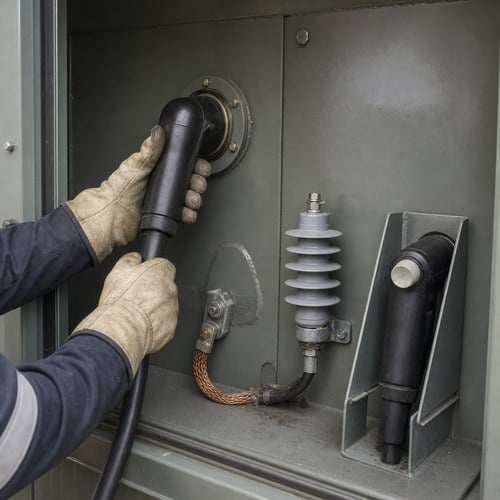
The failure a crew sees first is usually at the surge arrester, not inside the tank. A metal-oxide arrester is a resistor that only becomes conductive above its rated voltage. A sustained ferroresonant overvoltage parks it in conduction and converts the oscillation into heat inside a block of ceramic that was sized for microsecond impulses at a defined duty cycle. Eaton’s reference data on overvoltage protection for pad-mounted transformers states the limit plainly: arresters reduce overvoltages but do not eliminate them, and the higher the arrester duty cycle, the more conductive material is present and the longer it survives an overvoltage before failing. A light-duty distribution arrester that is perfectly adequate for lightning is not sized for minutes of power-frequency energy. Eaton reference data TC202005EN — Overvoltage Protection for Pad-Mounted Transformers (https://www.eaton.com/content/dam/eaton/products/medium-voltage-power-distribution-control-systems/cooper-power-series-transformers/overvoltage-protection-for-pad-mounted-transformers-information-tc202005en.pdf)
Behind the arrester the damage is quieter and harder to find on a routine test. Bushing surfaces show tracking where flashover occurred. Winding insulation punctures at the point where the oscillation peaks, and the puncture is often small enough that a turns ratio test still passes. The core runs hot, because the flux excursion is far beyond design and heat is what shortens insulation life. Arrester failure is usually the first casualty, not the only one.
There is also a symptom that is not electrical at all. A unit in ferroresonance frequently produces a low-frequency drone or rattle that sounds different from normal magnetostriction hum — uneven, irregular, and loud enough that crews notice it before any relay operates. Treat it as a signal, not a nuisance.
Single-Phase Switching Is the Trigger You Can Control
Of the four conditions, asymmetrical switching is the one a specifier can remove with a single line item. Single-phase switching of a three-phase transformer bank — whether from cutouts, one blown fuse, or a single-pole reclosing scheme — leaves the bank partially energized and capacitively coupled to the source, which is the classic initiator in cable-fed distribution systems.
IEEE Std C57.105-2019, the guide for application of transformer connections in three-phase electrical systems, treats these connection and switching interactions as a design consideration rather than an accident: IEEE Std C57.105-2019 (https://standards.ieee.org/ieee/C57.105/6121). The standard exists precisely because the interaction between a transformer connection and the circuit around it decides whether a system behaves or misbehaves.
What works in the field is unglamorous. Switch all three phases together with a gang-operated device instead of single-phase cutouts wherever the configuration allows. Where single-phase devices are unavoidable, keep a small permanent resistive load on the secondary during switching so the oscillation has something to dissipate into. A damping resistor or a ferroresonance suppression circuit across the winding is the next layer, and a surge arrester selected for temporary overvoltage rather than lightning alone is the last one.
None of this needs exotic hardware. It needs the switching scheme and the arrester duty cycle to be decided at the same time as the transformer rating, instead of after the cable has already been pulled.
Five Things to Put in the RFQ
Winding connection and grounding. Say whether a grounded-wye primary is acceptable. An ungrounded delta primary on a long cable run is the highest-risk arrangement there is, and the answer changes the whole overvoltage picture.
Primary switching device type. Gang-operated three-phase load-break switch, three-phase reclosing, or single-phase cutouts. If single-phase devices are unavoidable, state it, because it changes the surge arrester selection.
Arrester class, duty cycle, MCOV and temporary overvoltage capability. "Arresters included" is not a specification. Ask for an arrester sized against temporary overvoltage, not lightning alone.
Cable schedule. Conductor size, length and insulation type for every primary segment. Sheath capacitance is the other half of the resonant circuit and it is invisible on a nameplate schedule.
Secondary damping. Whether a small permanent load or damping resistor will be left on the secondary during switching, and how many percent of rating it represents.
What a Pad Mounted Transformer Manufacturer Asks Before You Order
On any project with long primary cable runs, the first document we ask for is not the nameplate schedule. It is the one-line diagram with cable lengths and the switching arrangement, because those two items decide whether the overvoltage risk is negligible or real. A pad mounted transformer manufacturer who quotes from the transformer list alone is quoting a unit, not a solution.
Every unit goes through a routine test sequence, and no-load loss and magnetizing current are recorded along the way. Those two numbers are the inputs that turn a ferroresonance question from an opinion into a calculation, and we will pass them to your consulting engineer before shipment on request.
Ryan Electric has manufactured distribution and power transformers since 2007, from a 120,000 m² manufacturing base with 180+ sets of production and test equipment and 37 patents. Since 2023 the company has operated as an official joint-venture partner of Eaton, which is one reason we treat arrester and switching coordination as part of the transformer scope rather than somebody else’s problem.
A pattern we see repeatedly on North American subdivision work is a small three-phase unit — 75 kVA to 500 kVA — at the end of a long underground lateral, fed through single-phase cutouts, serving a load that will not exist for another year. Every condition on the list is present at once, and the site is unloaded for months. When the specifier moves to a gang-operated switch and leaves a small resistive load on the secondary through commissioning, the arrester failures stop.
If you are specifying pad mounted units on a cable-fed system, send us the one-line diagram and the cable schedule before the order is placed. We will review the switching arrangement, the arrester specification and the secondary damping against your actual circuit, and tell you which of the four conditions you have — and which you have already designed out. That is the conversation a pad mounted transformer manufacturer should be having with you before the order is placed, not after the first arrester fails.
About the Author
This article was prepared by the Ryan Electric transformer engineering team. Ryan Electric (Jiangsu Ryan Electric Co., Ltd.) designs and manufactures cast resin and VPI dry type transformers, oil-immersed transformers and pad mounted units at its 120,000 m² manufacturing base, serving data center, industrial, utility and infrastructure projects across North America, Southeast Asia, the Middle East and Africa.