
 EN
EN
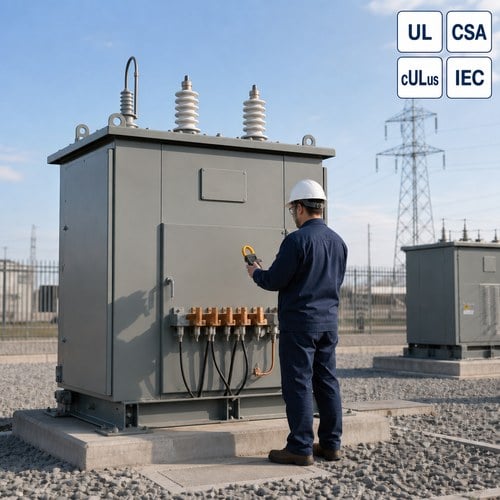
Last spring, a plant engineer in Ohio emailed us about a 13.8 kV loop feeding three production buildings. A phase-to-ground fault had been hunting through that system for two weeks — the protective relays saw almost nothing, because the loop was an ungrounded system with no zero-sequence path for fault current to return. By the time his contractor found the burned cable splice, two 500 hp motor drives had already failed on the healthy phases. The fix he ordered was a 15 kV class grounding transformer with a zigzag winding. His question to us was short: "What current rating do I put on the purchase order — 10 seconds or continuous?"
That question is more common than it should be, and it is exactly where specs go wrong. Here is what we tell buyers when that question shows up in their project.
What a Grounding Transformer Actually Does
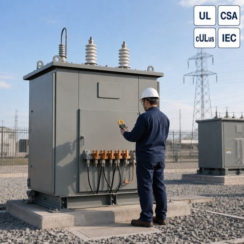
It is not a distribution transformer in the usual sense. A grounding unit like this carries almost no load in normal operation. Its job is to create an artificial neutral point on a system that does not have one — typically a delta-connected system, or a wye system whose neutral bushing is not available or not permitted to be solidly grounded.
When a phase-to-ground fault occurs on an ungrounded system, fault current has nowhere to flow except through the distributed capacitance of cables and windings, which is small. Protection therefore cannot clear the fault, and the system keeps running with one phase at ground potential while the healthy phases rise to full line-to-line voltage — roughly 1.73 times normal phase voltage, with transient overshoot possible during intermittent arcing. Motors and cables on the healthy phases take the stress, and insulation failures follow, often weeks later and far from the actual fault.
Connect a zigzag unit with its neutral grounded, and the picture changes. The winding offers a low-impedance zero-sequence path, fault current flows back through the transformer, and protective devices can finally see it and trip. In a zigzag (interconnected-star) winding, each phase carries roughly one third of the zero-sequence fault current, which is why these units are physically small relative to the load they protect.
Zigzag vs. Wye-Delta: Which Winding Belongs in Your Spec
Buyers ask us about two common ways to build a grounding transformer: the zigzag and the wye-delta.
| Comparison | Zigzag (interconnected star) | Wye-Delta |
| Normal load current | Near zero — magnetizing current only | Can also serve auxiliary delta load if specified |
| Zero-sequence impedance | Low, controllable by design | Low, set by winding geometry |
| Physical size | Compact, lowest cost | Larger, higher cost |
| Typical use | Pure grounding duty on 480 V to 34.5 kV systems | Grounding plus auxiliary or station service load |
| Common ratings | 400 A for 10 s; continuous for HRG duty | Often continuous-rated |
For a project whose only need is a neutral point, the zigzag transformer is almost always the right call — it is smaller, cheaper, and easier to mount inside an outdoor enclosure. We build both at our factory, but roughly nine out of ten grounding orders we ship are zigzag units. Specify wye-delta only when the unit must also feed an auxiliary load, such as a station service panel on the delta side.
Continuous vs. Short-Time Rating: The Spec Decision That Matters Most
This is the decision that caused the Ohio engineer's phone call, and it is the one most buyers get wrong.
A grounding transformer that works with a low-resistance grounded system is designed for short-time duty. The system's neutral grounding resistor (NGR) limits the ground fault current to a set value — commonly 400 A, sometimes 200 A or 600 A — and the protection scheme clears the fault within seconds. The transformer is therefore rated to carry that current for a defined duration, usually 10 seconds, per IEEE C57.32 test procedures. Rating a short-time unit "continuous" wastes money on copper and core; rating a continuous-duty unit "10 seconds" is a safety hazard.
On a high resistance grounding (HRG) system, the current is deliberately limited to about 5 A or 10 A and the system runs with the fault active while maintenance locates it. That unit must be rated continuous, because it carries current indefinitely. Mixing the two up in a spec is the single most common error we see in RFQs — a buyer writes "grounding transformer, 400 A" and forgets the duty cycle, then the factory quotes the wrong machine.
Ground the System First: Ungrounded, Solid, Low-Resistance, or HRG
Before anyone can rate a grounding unit, the system grounding philosophy has to be decided, because it sets the current, the duty, and the protection scheme.
- Ungrounded systems are legal in many industrial codes — NEC Article 250.21 still permits them — but they tolerate the first fault silently and expose healthy equipment to overvoltage. This is the configuration that usually drives buyers to add a grounding unit later.
- Solidly grounded wye systems do not need a grounding unit when the neutral is available and permitted. Zigzag units appear when the neutral is inaccessible or solid grounding is not allowed.
- Low-resistance grounded systems (typically 200–800 A, 10-second duty) are the standard choice for medium-voltage industrial distribution. A zigzag plus NGR gives reliable fault detection with limited damage at the fault point.
- High resistance grounded systems (5–10 A, continuous) keep the plant running through a single fault with an alarm, common on 480 V processes that cannot afford an unplanned trip. NEC 250.36 covers HRG on systems from 480 V to 1000 V.
For reference, the grounding practice that decides which of these fits your plant is described in the IEEE 142 recommended practice for grounding of industrial and commercial power systems, which we treat as the baseline whenever a client asks us to review their system philosophy.
What Must Be on the Spec Sheet
When you send an RFQ for a grounding transformer, a complete spec answers these items — and a quoting engineer can tell immediately when they are missing:
- System line-to-line voltage and frequency (for example, 13.8 kV, 60 Hz), and the BIL class required for the insulation system.
- Neutral grounding method: low-resistance with NGR current and time (400 A, 10 s), or HRG continuous duty (5 A or 10 A).
- Continuous or short-time rating, stated explicitly — never leave this to inference.
- Whether a neutral grounding resistor is included, and its ohmic value, because the zigzag alone does not limit current.
- Enclosure and environment: indoor, outdoor, pad-mounted style, or substation frame, plus temperature class.
- Applicable test standard — we build and test to IEEE C57.32, which covers requirements, terminology, and test procedures for neutral grounding devices, including temperature-rise and short-time current tests.
- Delta or zigzag winding arrangement, and whether the unit must carry any auxiliary load.
A zigzag transformer for a 15 kV class system, 400 A for 10 seconds, is a small, light machine compared with the distribution transformers around it. But "small" does not mean simple — the zero-sequence impedance, the insulation coordination at the neutral, and the short-time thermal withstand all have to be engineered, not improvised.
How We Build and Test Grounding Units at Ryan
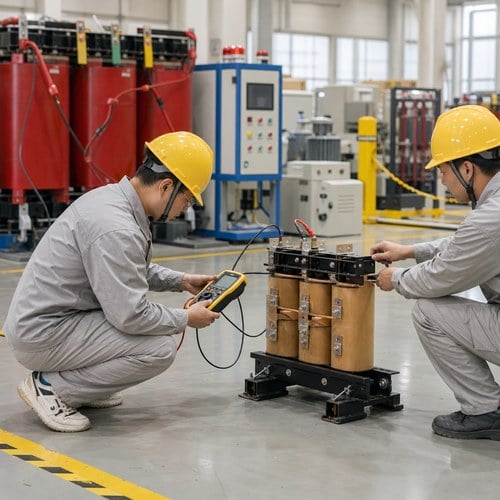
Since 2023 we have worked as an official joint-venture partner of Eaton, and that cooperation shapes how we treat specialty units like this one — they go through the same discipline as our main distribution line, not a side job. Our 120,000 m² factory runs 180-plus sets of equipment, and grounding transformers leave the floor only after a factory test report that includes turns-ratio, insulation resistance, applied and induced voltage tests, and, where the rating demands it, a short-time current test witnessed by our QA team.
One habit from the test floor: when a customer's RFQ says "grounding transformer" and nothing else, we call before quoting. In the past year we have caught specs that would have shipped a continuous-rated unit into a 10-second duty, and a zigzag ordered for a system that actually needed a wye-delta with auxiliary load. The questions take five minutes on the phone and save months of trouble later.
The Bottom Line for Buyers
If your facility runs an ungrounded medium-voltage system, or a delta system where a solid neutral is not available, a grounding transformer with a zigzag winding is the practical fix — it gives protection a zero-sequence path, limits overvoltage stress on healthy equipment, and lets relays finally see ground faults. Choose the winding based on whether you need auxiliary load capability, and choose the duty cycle based on your grounding method: 10-second ratings for NGR-limited low-resistance systems, continuous ratings for HRG.
Send us your system voltage, your grounding philosophy, and your fault-current target, and we will confirm the rating before you commit. Email [email protected] or request a quote through the contact page — the spec review is free, and it is the step that keeps an ungrounded system from becoming an unplanned outage.
About the Author
Ryan Electric is a transformer manufacturer in China founded in 2007, serving utilities, data centers, and industrial clients across North America, Southeast Asia, and the Middle East. This article was prepared by our engineering and content team, drawing on factory test experience and field feedback from transformer projects shipped worldwide.
Table of Contents
- What a Grounding Transformer Actually Does
- Zigzag vs. Wye-Delta: Which Winding Belongs in Your Spec
- Continuous vs. Short-Time Rating: The Spec Decision That Matters Most
- Ground the System First: Ungrounded, Solid, Low-Resistance, or HRG
- What Must Be on the Spec Sheet
- How We Build and Test Grounding Units at Ryan
- The Bottom Line for Buyers