
 EN
EN
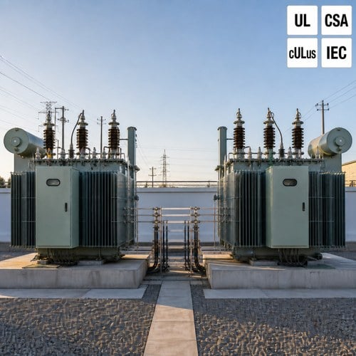
Two summers ago, a utility in Texas added a second 1,000 kVA pad-mounted transformer beside an existing unit to carry a growing residential feeder. The plan looked simple: parallel the secondaries on a common bus and let both units share the load. On paper the two nameplates matched. In the field, the first close-in attempt produced a loud hum, a blown fuse link on the low-voltage side, and a substation that stayed down for an afternoon. The cause was not bad hardware — it was an impedance mismatch nobody had checked before energizing. Parallel operation of transformers looks straightforward on a single-line diagram, and it punishes the details nobody verifies.
Why Utilities and Plants Run Transformers in Parallel
Running two units on one bus is not a special case anymore. Load grows faster than a single unit can be ordered and delivered, so owners stage capacity: install one transformer now, parallel a second when the feeder fills. Utilities parallel units to take one out for maintenance without dropping customers. Industrial plants parallel small units because two compact transformers fit a building where one large unit cannot. In every case the goal is the same — one bus, two sources, load shared automatically.
The catch: parallel units only divide load the way you expect if their electrical characteristics line up. Get one condition wrong, and the pair stops acting like a single 2,000 kVA bank and starts acting like two machines fighting each other. The failures show up as overheating, fuse operations, and protection trips — always at the worst moment, usually after the warranty conversation has ended.
The Conditions for Safe Parallel Operation of Transformers
Five conditions must hold before two transformers are connected to a common bus:
- Same phase sequence and same phase displacement (vector group). A Dyn11 unit will not parallel with a Dyn1 or a Yyn0 unit without a phase-angle problem.
- Voltage ratios equal at the operating tap, within about 0.5 percent. Off-nominal tap positions count — both units must sit on the same tap.
- Percent impedance closely matched, within roughly 10 percent of each other. The closer the %Z values, the fairer the load split.
- Compatible short-circuit capacity and protection. The bus, fuses, and breakers must handle the combined fault contribution of both units.
- Same system frequency and a common reference — two units designed for different grids have no business on one bus.
These read like textbook lines until a real project is on the table. What our engineers compare before any parallel proposal are the measured values from the routine test reports — not the nameplate promises. Measured %Z and measured ratio at the actual operating tap are what decide whether two units can share a bus safely.
Load Sharing and %Z: Where the Math Bites
The core rule of parallel operation of transformers is that load divides by impedance, not by goodwill. For two units of equal rating, the kVA each carries is inversely proportional to its own %Z: the unit with the lower impedance takes the larger share. Consider two 1,000 kVA units where the nameplates read 5.5 percent and 6.5 percent impedance. At a bank total of 2,000 kVA, the 5.5 percent unit tries to carry about 1,083 kVA — 108 percent of its rating — while the 6.5 percent unit loafs at 917 kVA. The lower-impedance unit reaches 100 percent load when the bank is only at roughly 1,846 kVA, about 92 percent of the capacity the owner paid for.
| Bank: two 1,000 kVA units | Mismatched %Z (5.5% / 6.5%) | Matched %Z (5.5% / 5.5%) |
| Load split at 2,000 kVA total | 1,083 kVA / 917 kVA (108% / 92%) | 1,000 kVA / 1,000 kVA (100% / 100%) |
| Usable bank capacity before one unit hits 100% | ~1,846 kVA (92%) | 2,000 kVA (100%) |
| Risk at full bank load | Lower-%Z unit overheats, ages fast, trips | None from impedance |
That is why two "identical" units with nameplate impedances a full point apart derate the bank before it is even energized. The fix is not a bigger fuse. It is either matching %Z in the specification — ask both factories for measured values at the principal tap — or accepting a lower bank rating and saying so in the protection settings.
For transformer load sharing, the same inverse rule applies to different ratings: each unit contributes its own rated kVA divided by its %Z, and the pair shares proportionally only when the %Z values are close. When an owner asks us whether a 750 kVA unit can parallel with a 1,000 kVA unit, our answer starts with the same question — what are the measured impedances, and which tap will both units run on?
Circulating Current: What Happens When Ratios Do Not Match
Voltage ratio mismatch creates a current that flows between two paralleled units even when the bus has zero load on it. Engineers call it circulating current, and it is limited only by the sum of the two unit impedances. As a quick check, a 2.5 percent tap difference across two units with 5.5 percent impedance each produces roughly 0.025 / (0.055 + 0.055) — about 23 percent of rated current circulating at no load. That current makes losses, heats both tanks, and pushes the winding temperature up for no useful work. A 0.5 percent ratio difference keeps the no-load circulating component near 5 percent, which is why the rule of thumb is "match the ratio within half a percent."
Ratio mismatch also distorts load sharing under load, pushing the higher-ratio unit toward overexcitation and the pair toward unbalanced heating. The phase-angle mistakes are worse: connecting units with incompatible vector groups is effectively a short circuit through the bus, and the protection operates before anyone has time to read the meter. Every parallel installation we have witnessed starts with a phase-sequence check at the bus — not because the engineers doubt the nameplates, but because one reversed cable is cheaper to find than one burned bank.
What to Verify on the Test Report Before Paralleling
Every unit we ship includes a routine test report with the numbers a parallel study needs. Before you parallel a new transformer with existing hardware, pull these five values from the reports of both units:
- Measured %Z at the principal tap, on the same base — not the guaranteed nameplate figure.
- Measured voltage ratio at the operating tap, including the off-nominal taps you plan to use.
- Vector group or phase displacement, plus a site phase-sequence check before the first close.
- No-load loss and load loss — they set the efficiency of the pair and reveal core or winding differences.
- Tap changer position and range, so both units can be set to the same tap and stay there.
The test procedures that produce these numbers are defined in IEEE C57.12.90, the standard test code for liquid-immersed transformers, and the rating and nameplate conventions come from IEC 60076-1, whose scope is on the IEC Webstore page. If a supplier cannot produce measured impedance and ratio data for the exact unit, that unit should not be the one you parallel with anything.

What We Check at Ryan Electric Before Two Units Ship
As an Eaton joint venture partner since 2023, with UL, CSA, IEEE, and DEKRA credentials in our portfolio, a 120,000-square-meter manufacturing base, and 37 patents behind us, we treat parallel-ready orders as a documentation exercise, not a promise. When a buyer tells us two units will run on one bus, we record the measured %Z at the principal and off-nominal taps, run the routine tests per IEEE C57.12.90, and state the impedance and ratio on the test report in a way the site engineer can use without a phone call back to the factory.
The practical advice is short. In parallel operation of transformers, the pair is only as good as the worst-matched parameter — and the worst-matched parameter is usually found in the fine print of a test report nobody compared. If you are adding a unit to an existing bank, send the old unit's test report together with your RFQ, and we will run the impedance and ratio comparison before we quote. That single step has caught mismatches that would have derated a bank or burned a fuse on day one.
Planning to parallel a new transformer with existing equipment? Send your existing unit's test report and the new rating through ryantransformers.com — our engineers will check %Z, ratio, and vector group compatibility and quote you units that share the load the way the single-line diagram promises.
About the Author — This article was written by the engineering team at Ryan Electric, an Eaton joint venture partner and UL/CSA-certified transformer manufacturer in Jiangsu, China, serving utility, renewable, and industrial clients across North America, Southeast Asia, the Middle East, and Africa.
Table of Contents
- Why Utilities and Plants Run Transformers in Parallel
- The Conditions for Safe Parallel Operation of Transformers
- Load Sharing and %Z: Where the Math Bites
- Circulating Current: What Happens When Ratios Do Not Match
- What to Verify on the Test Report Before Paralleling
- What We Check at Ryan Electric Before Two Units Ship