
 EN
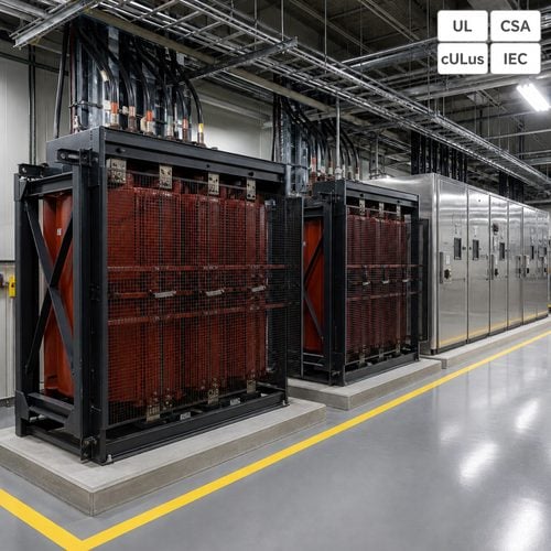
Four halls at 60 MW each, a utility that offers 13.8 kV because that is the line already running past the site, and a switchgear package ordered before anyone ran the fault calculation. Six months later the lineup no longer fits the electrical room, the feeder count has doubled, and the available fault current at the 480 V bus sits above the rating of equipment that cannot be returned. None of that was a transformer failure. The campus picked a medium voltage class before calculating what the choice would cost in copper, switchgear and floor space.
A data center transformer is usually treated as the last item on the single line, a ratio that turns 34.5 kV into 480Y/277 V. In practice the primary voltage class is a system decision that reaches into cable schedules, switchgear ratings, arc flash studies and, since 2024, the scope of US efficiency regulation. Getting it right at the concept stage costs a week of engineering. Getting it wrong costs a switchgear re-order.
What follows is how we compare the two classes with clients, the numbers we ask for before quoting, and the three specification points that decide whether the unit performs for twenty-five years or becomes a warranty argument in year three.
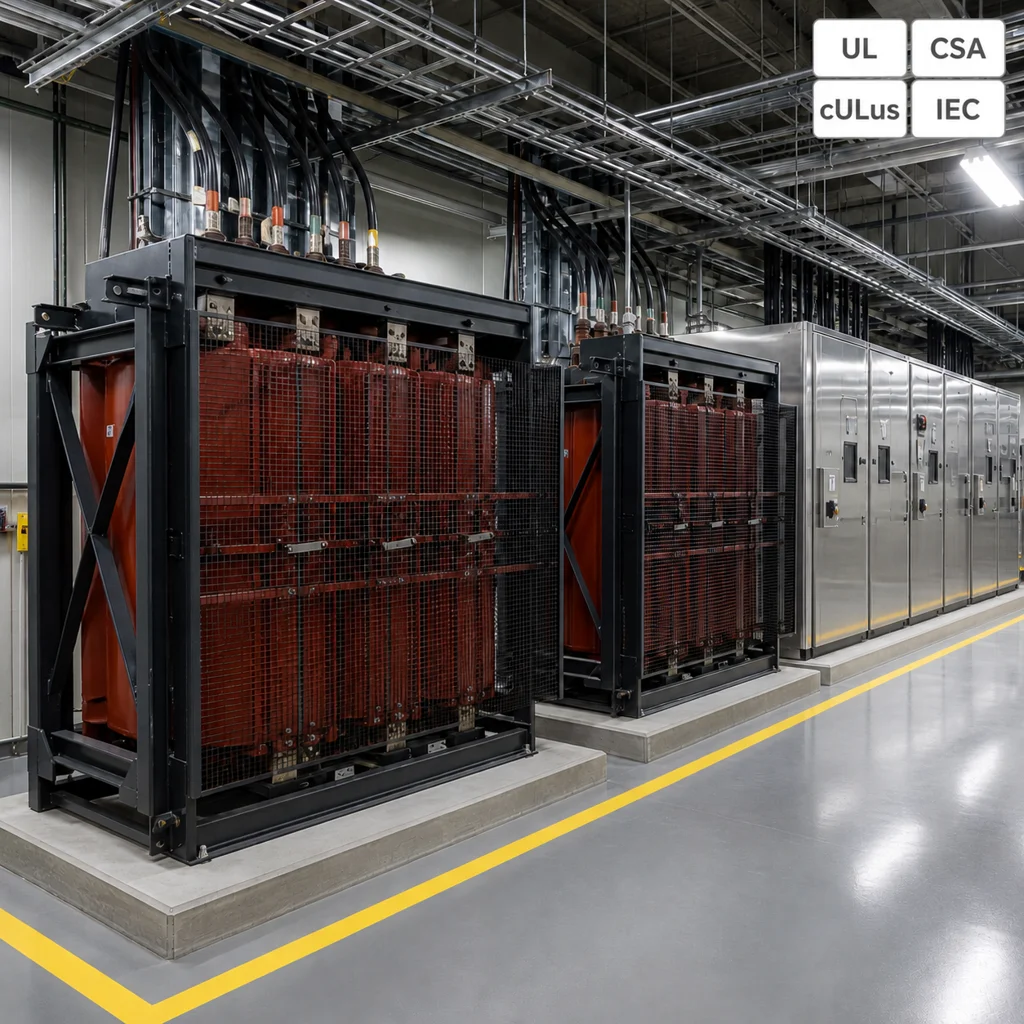
Why a Data Center Transformer Spec Starts at the Voltage Class
Transformer ratio is the first lever, and it is pure arithmetic. For a given MVA, current falls in inverse proportion to voltage. A 60 MW hall draws about 2,510 A at 13.8 kV and about 1,004 A at 34.5 kV. That 2.5 to 1 ratio shows up in the ampacity of every feeder between the utility point of connection and the unit substation, in the number of parallel runs per feeder, and in the width of the cable tray above them.
Fault current moves in the other direction. With a 500 MVA source behind the meter, a bolted fault at the 13.8 kV bus is roughly 20.9 kA; at 34.5 kV the same source delivers about 8.4 kA. Lower fault current lets the campus use a lower interrupting rating on the medium voltage switchgear, which matters in a market where switchgear lead time is running longer than transformer lead time.
Here is the part that gets missed in the kickoff meeting. 34.5 kV gear is not physically smaller than 13.8 kV gear — clearances are longer and the standard basic insulation level is 200 kV against 95 kV for the 13.8 kV class, so the cubicles are taller and deeper. What the higher class buys is lower current per megawatt and a lower fault level, which shrinks the number of feeders and the rating of the devices at campus scale. Those are two different savings, and only one of them shows up in a cable schedule.
34.5 kV and 13.8 kV Side by Side
The comparison below uses a 60 MW hall and a 500 MVA available source. Change either input and the conclusion can move, which is why we ask for the utility fault letter before we quote a medium voltage transformer for a campus.
Current for the hall, fault level at the bus, insulation level, feeder count and switchgear footprint all move together. A campus that cuts the feeder count in half usually finds the saving in cable and terminations rather than in the transformer itself.
| Parameter (60 MW hall) | 13.8 kV | 34.5 kV |
| Current at full hall load | ~2,510 A | ~1,004 A |
| Fault current, 500 MVA source | ~20.9 kA | ~8.4 kA |
| Standard basic insulation level | 95 kV | 200 kV |
| Primary feeders per hall | More parallel runs | Fewer runs |
| Switchgear clearances | Shorter, more cubicles | Longer, fewer cubicles |
Neither column wins on its own. If the utility will only deliver 13.8 kV, a campus can still step up internally to 34.5 kV and distribute at that level — but every conversion adds a transformer, roughly one percent of throughput in losses, and one more asset to maintain. That trade is worth modelling rather than assuming.
Impedance Decides What Happens at the 480 V Bus
Percentage impedance is where transformer impedance stops being a ratio and starts being a protection problem. Take a 2,000 kVA unit at 5.75 percent impedance with a 480Y/277 V secondary. Bolted fault current at the secondary terminals is about 41.8 kA before cable impedance and motor contribution are added: 2,000,000 divided by (1.732 × 480 × 0.0575).
Raise the impedance to 6.5 percent and the number falls to roughly 37 kA. Buyers sometimes read that as a safety gain. It is not automatically one. Incident energy depends on current and clearing time together, so a lower fault current sitting below the instantaneous trip threshold of the upstream device can lengthen the arc duration and raise the hazard. That is why the arc flash study has to be run against the actual unit rather than a typical value; the working rules live in NFPA 70E, current edition 2027.
The other half of the transformer impedance story is tolerance. Guaranteed impedance is normally held to plus or minus 7.5 percent, so two units ordered to 5.75 percent can differ from each other by nearly 15 percent at the extremes. Put those two in parallel and the mismatch drives circulating current and unequal loading long before either reaches nameplate. If the design depends on parallel operation, specify the impedance window, not just the nominal value.
Two-Winding, Three-Winding or Primary-Selective
Three arrangements cover most campus designs. A two-winding unit substation is one transformer per hall, the simplest to protect and the easiest to replace. A three-winding unit takes one primary and feeds two secondary buses, which cuts medium voltage switchgear and cable but couples the halls electrically — a trip on one secondary takes both down unless the protection scheme is built for it. A primary-selective arrangement brings two utility feeds into one transformer through a selector: source redundancy, and no transformer redundancy at all.
For a Tier III or Tier IV topology the decision is usually made for you. Redundancy has to sit at the transformer, not only at the source. Two 2,000 kVA units each loaded near half rating also run cooler than one 2,000 kVA unit at full load, because no-load loss scales with core size while load loss scales with the square of current. The premium is in the second core, not in the copper.
Where budget is tight, the honest compromise is a spare unit in the warehouse rather than a spare unit installed. In a market where a 34.5 kV dry type transformer can sit in a production queue for a year, a spare on the shelf is a scheduling decision, not an electrical one.
Harmonics, K-Factor and the Neutral Conductor
Server power supplies have improved, but they have not become linear. A modern switched-mode supply with active power factor correction draws current with a high crest factor and an odd harmonic spectrum that reaches well past the seventh. The triplen harmonics — third, ninth, fifteenth — add in the neutral instead of cancelling, so the neutral can carry more current than the phase conductor it belongs to.
A K-factor transformer is rated to tolerate the extra eddy and stray loss that spectrum produces in the windings. K-13 covers a mixed office and data load; K-20 is the usual choice for a hall packed with dense server supplies. What a K rating does not do is reduce voltage distortion on the bus. That is a system problem, governed by the 5 percent total harmonic distortion planning level at the point of common coupling in IEEE 519 for systems at or below 69 kV, and solved with multi-pulse rectifiers, active filters or a larger neutral.
Our specification default for a data center transformer is a K-13 winding as the minimum, a 200 percent neutral and a harmonic loss calculation run against the measured spectrum rather than a generic K number. That calculation is what tells you whether a 2,000 kVA frame is really a 2,000 kVA frame at this load.
The DOE 2029 Line Sits at Exactly 34.5 kV
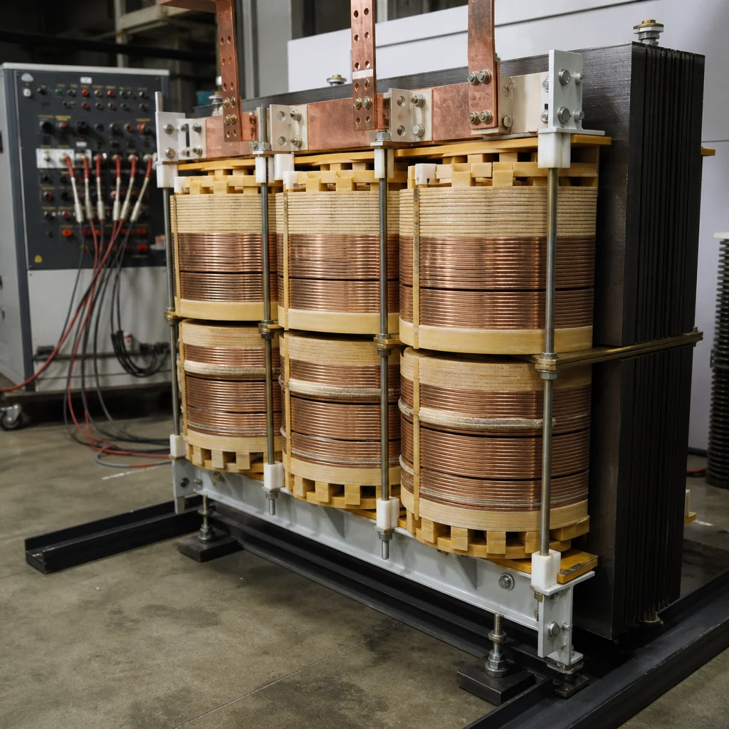
US efficiency regulation draws a boundary that most campus teams discover late. A distribution transformer, as defined in 10 CFR 431.192, has an input voltage of 34.5 kV or less, an output of 600 V or less, a 60 Hz rating, and a capacity between 10 and 2,500 kVA for liquid-immersed units or 15 and 2,500 kVA for dry type transformer units. The definition and the compliance dates are published by the US Department of Energy.
Two consequences follow. A 34.5 kV to 480Y/277 V unit substation is a distribution transformer and must meet the efficiency table, while a 34.5 kV to 4.16 kV unit is a power transformer and falls outside it. And the amended standards adopted in the 2024 final rule apply to units manufactured on or after 23 April 2029, so a campus energizing in 2029 or 2030 is already specifying into the new table whether or not the tender says so.
Compliance is bought mainly in core steel. Meeting the 2029 no-load loss limits usually means a larger core, better grain-oriented or amorphous material, and a heavier unit — which changes shipping weight, floor loading and the structural steel underneath. A tender written today with no loss package against the 2029 table is a change order waiting for a date. Ask every bidder to quote both tables so the delta is visible before the purchase order, not after.
What We Build and How We Verify It
Ryan Electric has manufactured transformers since 2007 from a 120,000 m² plant in Haian, Jiangsu, with more than 180 sets of production and test equipment and 37 patents across dry type and liquid-immersed designs. Units are built to UL, CSA, IEEE, IEC and DEKRA schemes with CNAS-accredited testing, and since 2023 the company has operated as an Eaton joint venture partner.
For a 34.5 kV class dry type transformer, the tests that matter at this voltage are not negotiable. Impulse withstand at the 200 kV basic insulation level proves the winding insulation coordination. Partial discharge on cast resin is held to 10 pC or better at 1.5 times rated voltage; a unit that passes casually at 50 pC will still pass a factory acceptance test and then track in service. Temperature rise confirms the insulation class margin at the specified ambient, and ratio, impedance and sound level confirm that the unit on the truck matches the model that was studied.
When a 34.5 kV campus specification reaches our application desk, the first two questions are the utility available fault current at the point of connection and the measured harmonic spectrum of the UPS and server load. Neither appears on a typical kVA table, and both move the design. That conversation has taken more than one project from a single large unit to a pair of smaller K-rated units, and it has also stopped projects from paying for a K-20 winding they did not need.
If you are freezing a single line for a data center transformer this quarter, send the hall megawatts, the utility fault letter and the load spectrum. We will return a side-by-side comparison of both voltage classes, the medium voltage transformer and switchgear consequences, and a loss package against the 2029 table. Start here: contact our engineering team.
About the Author: This guide was written by the power engineering team at Ryan Electric (Jiangsu Ryan Transformers), a transformer manufacturer based in Haian, Jiangsu, China, supplying dry type, liquid-immersed and unit substation transformers to data center, utility and industrial projects worldwide.
Table of Contents
- Why a Data Center Transformer Spec Starts at the Voltage Class
- 34.5 kV and 13.8 kV Side by Side
- Impedance Decides What Happens at the 480 V Bus
- Two-Winding, Three-Winding or Primary-Selective
- Harmonics, K-Factor and the Neutral Conductor
- The DOE 2029 Line Sits at Exactly 34.5 kV
- What We Build and How We Verify It