
 EN
A platform contractor once sent us a 132 kV export unit specification with ninety pages of electrical requirements and one line about transport: maximum lift weight, 240 tonnes. Our first design weighed 262 tonnes oil-filled. We rebuilt the tank, split the conservator and shipped at 238. The electrical specification never changed. The number that decided the design was a crane limit.
Offshore wind keeps setting records that land-based procurement teams have not caught up with. In 2025, 9.3 GW of new offshore capacity was grid-connected worldwide, bringing the global total to 92.5 GW, and the average turbine installed passed 10 MW for the first time, according to GWEC's Global Offshore Wind Report 2026. Every megawatt in that figure passes through at least two transformers: a step-up unit at the turbine or array platform, and an export transformer that lifts the collection voltage to 132 kV or 220 kV for the submarine cable.
Most export units ordered today are specified like a land-based power transformer with a heavier paint system. That is where projects get hurt. Three constraints separate an offshore wind transformer from anything that sits in a fenced yard onshore: salt, weight, and the harmonic signature of power electronics.
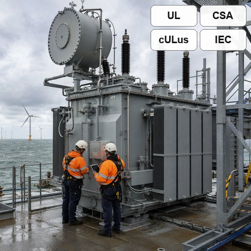
Collector Duty and Export Duty Are Not the Same Job
A collector transformer works at 33 kV or 66 kV and sees the combined output of eight to fifteen turbines. An export transformer steps that collection voltage up to transmission level — typically 132 kV, 220 kV or 275 kV — and carries the entire wind farm through one asset. On a 1 GW project that usually means two or three units in the 300 MVA class running in parallel, or a single 400 MVA unit backed by a spare strategy most owners cannot justify.
The duty profile is what changes the design. A land-based generator step-up unit at a thermal plant runs at a steady 85–95% load for decades. An offshore unit follows the wind: 40% average loading, long stretches at 20%, then weeks at 100% when the wind blows and the export cable is available. Thermal cycling of that amplitude works the insulation and the clamping structure in a way a base-load unit never experiences. We set winding clamp pressure and core bolt torque for cyclic duty rather than continuous duty for exactly this reason.
Impedance is the quiet decision. A 12.5% impedance on a 180 MVA, 220/66 kV unit limits fault current at the platform switchgear, but it also increases voltage drop under load and absorbs reactive power the platform has little room to replace. Impedance therefore has to be agreed with the cable and switchgear engineers before the transformer design is frozen. Note also that IEC/IEEE 60076-16 covers transformers for wind turbine applications up to 72.5 kV; the export unit normally falls outside its scope and is specified to IEC 60076-1 with a project supplement.
Salt Spray: Corrosion Protection Is a Specification, Not a Paint Colour
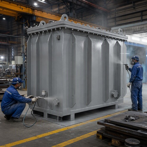
Offshore atmosphere is classified C5-M or CX under ISO 12944. The classification is not decoration: it sets a minimum dry film thickness, a coating system and a test duration — usually 1,440 hours of neutral salt spray for C5-M and considerably more for CX. A tank painted to a land-based C3 system will show blistering at the weld toes within two or three years on a North Sea platform.
A workable C5-M system is a zinc-rich primer at roughly 80 µm, an epoxy intermediate coat at 120 µm and a polyurethane topcoat at 60 µm — about 260 µm total. For CX the same stack moves to 320 µm or more, with stripe coats on every weld, bolt and edge, because those are the places where corrosion protection thickness collapses first.
Paint is half the job. Hot-dip galvanized or 316 stainless hardware, isolation washers between stainless fasteners and aluminium coolers, a breather that keeps salt-laden air out of the conservator, and IP66 cabinets for monitoring equipment belong in the same clause. In our factory the argument with platform contractors is almost never about the winding. It is about whether the nameplate bracket, the earthing bosses and the cable gland plate were included in the coating schedule.
Weight and the Platform Interface
A platform deck has a hard weight budget set by the topside structure and the installation vessel crane. The transformer is usually the heaviest single item on that deck, and every kilogram above the lift limit has to come out of the design — it cannot be negotiated with the crane operator. Table 1 gives a realistic breakdown for a 180 MVA, 220/66 kV export unit. The numbers are typical rather than universal, but the proportions hold.
| Component | Typical mass (t) |
| Core and windings | 104 |
| Tank, cover and stiffeners | 42 |
| Insulating oil | 58 |
| Radiators and cooling fans | 12 |
| Bushings and accessories | 6 |
| Base frame and jacking pads | 4 |
| Total, oil-filled | 226 |
Two decisions follow from that table. First, whether the unit travels oil-filled or oil-drained with the oil in drums. Draining removes 50–60 tonnes from the lift, which can be the difference between a standard and a heavy-lift crane; the price is nitrogen blanketing, transport bracing and a longer commissioning sequence on the platform. Second, where the centre of gravity sits. CoG marking, lifting lug positions and jacking pads are interface data the structural engineer needs at drawing review, not at shipment.
Transport loads are their own design case. Project specifications commonly call for 3 g vertical and 2 g longitudinal acceleration during sea transport, which is more severe than the seismic case at most European sites. Core clamping, winding clamping and the internal bracing of the tank all have to be checked against it, and the check belongs in the design report rather than in a shipping note.
Converter Harmonics and Thermal Margin
An export transformer on a modern offshore wind farm rarely sees a clean sine wave for long. HVDC links, STATCOMs and the turbine converters inject harmonics that heat the windings through eddy losses, and the spectrum changes with network configuration. IEEE C57.110 sets out the harmonic loss factor calculation; the practical output is either a derating or an upgraded cooling class.
Here is the part most buyers miss. The cooling class is not a fixed label. An ONAN/ONAF unit that carries 180 MVA with fans running may carry only 130 MVA with the fans off. If the platform requires N+1 fan redundancy, the transformer has to demonstrate its rating with one cooling group out of service — and that requirement changes radiator area, tank dimensions and, eventually, the weight the crane has to lift. Cooling, weight and rating are one problem, not three.
Temperature rise is the number to hold a supplier to. A 65 K rise on a 40°C ambient looks generous until the unit sits inside an acoustic enclosure where local air reaches 50°C. Offshore units often need a 60 K design or an explicit ambient correction in the guarantee, because the difference between 60 K and 65 K is roughly eight percent of continuous rating. Converter harmonics make that margin matter more, not less: harmonic losses land in the same hot spot the guarantee is written against.
Factory Tests That Actually Predict Offshore Survival
A routine test certificate proves the unit matches its design. It does not prove the unit will survive twenty-five years of salt and thermal cycling. For offshore work the factory acceptance test on an offshore wind transformer should include the items below, witnessed by the owner's engineer or a third party such as DNV or Bureau Veritas.
• Ratio and polarity on every tap, plus winding resistance per phase
• Impedance and load loss at 100% and 50% rated current, and no-load loss and current
• Temperature rise at 100% and 110% rating, with the winding gradient recorded
• Partial discharge at 1.3 Um/√3, with a 100 pC limit for oil-immersed units
• Lightning impulse on the HV winding, and a tank vacuum and pressure test
• Sound level at 1 m, typically 75–80 dB(A) at this rating
• Oil dielectric strength, plus DGA sampling after the temperature-rise test
Two of those deserve more attention than they usually get. Partial discharge is the best single indicator of insulation defects that surface after a year of cycling. DGA after temperature rise — not before — catches local overheating the thermocouples never saw. We run both on every export-class unit and put the measured values in the report instead of a pass mark.
What to Put in the Offshore Wind Transformer Specification
If you are writing the specification for an offshore wind transformer, these five clauses do more work than another page of general requirements.
• Transport weight limit and the crane lift radius, stated as a hard number with the oil condition defined.
• Coating system by ISO 12944 category, with total DFT, stripe coat requirement and salt spray duration.
• Cooling redundancy expressed as a rating with one cooling group out of service, at the platform's real ambient.
• Harmonic spectrum from the converter and HVDC supplier, with the loss factor calculation required in the bid.
• FAT witness rights, the PD limit, and the DGA sampling point after the temperature-rise test.
Where Ryan Electric Fits
We have built oil-immersed and dry-type transformers in Jiangsu since 2007, on a 120,000 m² site with more than 180 sets of production and test equipment and 37 patents covering winding and cooling design. Since 2023 we have operated as an official Eaton joint venture partner, which put our documentation and process control under a partner audit regime rather than a customer audit regime.
For coastal and offshore projects the coating is applied in-house, so the C5-M system and the stripe coats stay under our control, and every export-class unit goes through partial discharge measurement and post-temperature-rise DGA before it leaves the bay. Our engineers will review a platform interface drawing set with your structural and cable teams before the tank design is frozen. The earlier that conversation happens, the cheaper the weight saving is.
If you are specifying an offshore wind transformer or a coastal export unit, send the rating, the platform weight limit, the ambient temperature and the harmonic spectrum. We will return a weight breakdown, a coating schedule and a test plan — the three documents that decide whether the unit fits the platform before anyone argues about price. Reach the team through ryan-transformers.com or at [email protected].
About the Author: This article was written by the transformer engineering team at Ryan Electric (Jiangsu Ryan Transformers), an Eaton joint venture partner and UL/CSA-certified manufacturer of oil-immersed, dry-type and pad-mounted transformers serving utility, renewable and industrial projects in North America, Europe, the Middle East and Southeast Asia.
Table of Contents
- Collector Duty and Export Duty Are Not the Same Job
- Salt Spray: Corrosion Protection Is a Specification, Not a Paint Colour
- Weight and the Platform Interface
- Converter Harmonics and Thermal Margin
- Factory Tests That Actually Predict Offshore Survival
- What to Put in the Offshore Wind Transformer Specification
- Where Ryan Electric Fits