
 EN
A crew in central Oklahoma opened a pad-mounted unit last November that had tripped its feeder twice in one week. The transformer was healthy. A squirrel had bridged the high-voltage bushings, flashed over, and left a carbon track that re-struck on every reclose. Two trips, one animal, zero winding faults, and a reliability report that still counted the unit as the problem.
We build these units, so treat the bias with suspicion. But the pattern is hard to argue with: most pad-mount callouts we are asked about do not start inside the tank. They sit at the boundary, in the fuse that protects the transformer and in the compartment that is supposed to keep wildlife out of it.
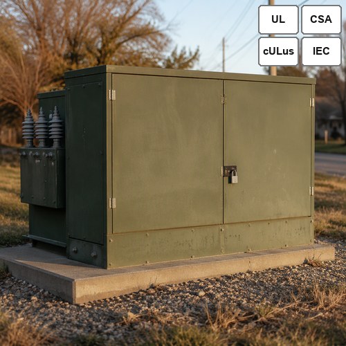
Two Failure Modes That Account for Most Pad-Mount Callouts
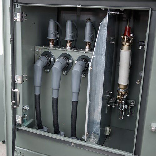
Pad mounted transformer fusing is the first. The primary fuse is the only device standing between a secondary fault and a transformer that has to be replaced on a lead time measured in months. Size it too small and it opens on cold-load pickup every time a feeder recloses after a storm. Size it too large and it sits above the through-fault curve, which means the transformer absorbs faults the fuse was supposed to clear.
The second is wildlife. Bushing wells, barrier boards, and the gap between the enclosure roof and the cable compartment are all entry points. A raccoon passes through a 75 mm opening without slowing down. A snake does not need an opening at all if the cabinet has a cable trench below grade.
Neither failure shows up in a routine electrical design review, because both live between the transformer specification and the utility's protection settings. As a pad mounted transformer manufacturer, the questions that reach us in the last two weeks before shipment are almost always about these two.
Read the Through-Fault Curve Before You Read the Fuse Table
Every fuse size decision starts from a curve, not a table. IEEE C57.109 defines how long a liquid-immersed transformer can carry a given multiple of rated current before damage accumulates; the scope and status are on the IEEE C57.109-2018 page. The guide presents coordination curves for four transformer categories, and the curves account for both thermal duty and the mechanical stress a fault puts on the windings.
Here is the number that makes it concrete. Take a 1,000 kVA unit with a 12.47 kV delta primary, a 480 V secondary, and 5.75% impedance. Primary full-load current is 46 A. Secondary full-load current is 1,203 A, and a bolted fault at the secondary terminals drives roughly 20.9 kA before cable impedance is counted. The fuse has to clear that fault before the primary current seen by the transformer crosses its C57.109 curve, and it also has to ride through the magnetizing inrush of the next energization.
Those two requirements pull in opposite directions. That tension is the whole job, and it is why a fuse schedule copied from a previous project is a liability rather than a shortcut.
The Three Numbers Behind a Bayonet Fuse Choice
Most North American pad-mounts use a NEMA Type B bayonet fuse in the high-voltage compartment, and the ratings stocked by most utilities run from 8 A to 200 A. Three numbers decide which one goes in.
Full-load current. From nameplate kVA and primary voltage, not from the drawing of the unit it replaces. The 46 A above is typical for 1,000 kVA on a 12.47 kV system.
Cold-load pickup. After an outage, every thermostat, compressor, and drive restarts at once. Inrush plus cold load can pull several times FLA for a few tenths of a second, which is why a fuse set at 1.2 times FLA becomes a nuisance-trip generator on a cold morning.
Upstream coordination. The recloser's fast curve must operate before the fuse for temporary faults, and the fuse must operate before the recloser's slow curve for permanent ones. Where the two share a point on the time-current plot, the utility gets the worst outcome available: a blown fuse on a fault the recloser could have cleared.
In practice, most utility standards land between 1.5 and 2.5 times primary FLA for the bayonet fuse, then verify the result against the through-fault curve. That range is a starting point. A unit feeding a large motor load and a unit feeding a strip center do not deserve the same answer, and the pad mounted transformer fusing schedule should show which assumption was used.
One more detail that costs nothing: ask for the fuse curve on the same sheet as the transformer damage curve. When those two lines are printed together, a miscoordination is visible in five seconds. When they are in separate documents, it is visible in year three.
Wildlife Protection Is a Spec Item, Not an Accessory
Transformer wildlife protection is usually treated as a line item a utility adds after the transformer is on the pad. It belongs in the specification instead, because the cheapest place to solve it is the factory floor.
IEEE 1656 sets out how wildlife protective devices should be tested for electrical, mechanical, and durability performance on distribution systems rated up to 38 kV, and the IEEE 1656-2010 record is the reference to quote when a supplier claims a cover will survive a decade outdoors. The test sequence answers that question. A datasheet does not.
The measures that actually change the outage count:
Insulated bushing wells and covers. On 15 kV and 25 kV units, covers that stay seated through a cable pull, not the slip-on type that leaves with the first windstorm.
Barrier boards between compartments. Full height, fitted before the tank closes. A climbing animal that gets inside should still not reach a live part.
Screened ventilation openings. Stainless mesh at every louver and at the base, sized to a 12 mm probe rather than to whatever the fabricator has on the shelf.
Sealed cable trench interface. A removable screen at the trench entry is the difference between an enclosure and a highway for snakes.
None of these add meaningful cost at the design stage. All of them cost a crew, a switching order, and an outage to retrofit.
What Changes in the Factory
Ryan Electric has built distribution transformers since 2007 on a 120,000 m² site with more than 180 sets of production and test equipment and 37 patents. Since 2023 the company has operated as an official joint-venture partner of Eaton, which is the credential North American utilities tend to ask about first. Units are UL listed, can be built to CSA C22.2 requirements for Canadian projects, and ship with routine test data to IEEE C57.12.90 in the factory acceptance package.
For pad-mount orders we build the wildlife package into the base design instead of quoting it as an option: 316 stainless hardware on the cabinet, epoxy-coated bushings, barrier boards fitted before the tank closes, and screened louvers verified against a 12 mm probe. As a pad mounted transformer manufacturer working to UL and CSA requirements, we would rather argue about a screen detail at the drawing stage than explain a snake entry at commissioning.
Fusing is where a pad mounted transformer manufacturer should ask the most questions. We want the utility's protection study, or at minimum the recloser curves and the available fault current at the pad. One order left our plant with a 200 A bayonet on a 500 kVA unit because the fuse schedule came from a larger project; it was caught during commissioning, and the two-week delay cost more than the transformer's freight.
A Short Checklist Before You Approve the Drawing
Six lines, and most pad-mount protection problems disappear before the unit leaves the plant.
1. Primary full-load current calculated from nameplate kVA and nominal system voltage.
2. Fuse size between 1.5 and 2.5 times FLA, then checked against the IEEE C57.109 curve at the available fault current.
3. Cold-load pickup profile confirmed with the utility's load research data, especially on feeders with electric heat or irrigation load.
4. Recloser fast and slow curves plotted on the same time-current sheet as the fuse.
5. Wildlife package specified by test standard, not by description. Ask for the IEEE 1656 test sequence or an equivalent.
6. Barrier and screen details shown on the approval drawing, including the cable trench interface.
The Cost of Getting It Wrong
A miscoordinated fuse does not fail dramatically. It opens, a crew replaces it, and the log records a transient outage. Do that three times on the same feeder in one season and the utility has spent more on labor and switching than the coordination study would have cost. The transformer wildlife protection package follows the same arithmetic: a screen costs tens of dollars, and a snake across the secondary terminals costs a week of lost service plus a replacement unit pulled from a committed production slot.
That is the argument for settling both details at the drawing stage. A pad mounted transformer manufacturer can change a barrier board before the tank closes for almost nothing. After the unit is on the pad, the same change becomes a field modification with an outage attached to it.
If you are specifying pad-mounted distribution units for a 2027 delivery window, the protection and wildlife details are worth closing now. Factory lead times are long enough that a drawing change after release costs what it did not cost five years ago.
Next Step
Send us the single-line diagram, the recloser curves, and the available fault current at the pad. Our engineering group will return a fuse schedule and a wildlife package matched to your standard, usually within three working days.
About the Author
This article was prepared by the sales engineering group at Ryan Electric (瑞安电气), a transformer manufacturer producing pad-mounted, dry-type, and oil-immersed units for utilities and EPC contractors in North America, the Middle East, Southeast Asia, and Africa. The group supports projects from specification through factory acceptance testing. Technical questions on this article can be directed to the sales engineering team through ryantransformers.com.
Table of Contents
- Two Failure Modes That Account for Most Pad-Mount Callouts
- Read the Through-Fault Curve Before You Read the Fuse Table
- The Three Numbers Behind a Bayonet Fuse Choice
- Wildlife Protection Is a Spec Item, Not an Accessory
- What Changes in the Factory
- A Short Checklist Before You Approve the Drawing
- The Cost of Getting It Wrong
- Next Step