
 EN
A school campus in southern Ontario removed its gas boilers in the summer of 2026 and replaced them with 420 kW of air-source heat pumps. The mechanical engineer sized the compressors correctly. The electrical package still failed on the first cold morning: the lead compressor start pulled the 1,200 A main down to 398 V, and two rooftop VFDs tripped on undervoltage before the second stage ever came on. The transformer for heat pump electrification is rarely the line item anyone argues about on a retrofit drawing, and that is exactly why it ends up under-specified.
Electrification Retrofits Break Transformer Assumptions
A gas boiler and a heat pump deliver the same heat. On an electrical drawing they have nothing in common. The boiler drew a few hundred watts for a circulator and a burner control. The heat pump pulls hundreds of kilowatts through hermetic motor-compressors, and it pulls them in blocks: start, stage up, defrost, stage down.
Existing services were sized around a summer cooling peak and a diversified lighting load. A heating retrofit moves the peak to a winter morning, when lighting and plug loads are also near maximum, and it converts a thermal load into a motor load. That is where the transformer for heat pump electrification decision actually begins, not at the compressor selection table.
There is a third change that load calculations routinely miss. The original service calculation carried demand factors a utility approved for a gas-heated building, with its short winter peak and low motor content. Re-applying those same diversity assumptions to a heat pump plant understates the load, because staged compressors do not diversify the way receptacle and lighting loads do.
The Load Math: What Heat Pumps Actually Ask From the Service
Start with design-day capacity, never nameplate capacity. A nominal 420 kW air-source plant in southern Ontario may deliver 420 kW at 8.3°C and only about 68% of that at a -15°C design condition. Published capacity tables show the drop; what they show less clearly is that electrical input climbs at the same time, because COP falls from roughly 3.4 to 1.8.
Here is the arithmetic from the campus above, which is typical of a mid-size commercial retrofit at 480 V:
- Heat pumps, 2 modules x 210 kW: 233 kW electrical at -15°C, COP 1.8
- Circulation pumps, 4 constant-speed: 22 kW, continuous
- Controls and BMS: 4 kW, continuous
- Resistance backup, 4 stages: 120 kW, only below design temperature
- Design electrical total: 379 kW, about 407 kVA at 0.93 power factor
That 407 kVA is the load. It is not the transformer size. The distance between those two numbers is where retrofit budgets go wrong in both directions, and the next section is about closing it without buying 40% more copper than the building will ever use.
Sizing the Transformer for Heat Pump Electrification
NEC Article 440 governs motor-compressor circuits and asks for rated-load current rather than nameplate current on hermetic refrigerant compressors. Feeder and service totals still run through Article 220, and NFPA 70 is the text your inspector will actually read. Practically: build the transformer size from a calculated load that includes compressor rated-load currents, the staged backup heat, the inrush current that starting those compressors creates, and the building load that stays connected.
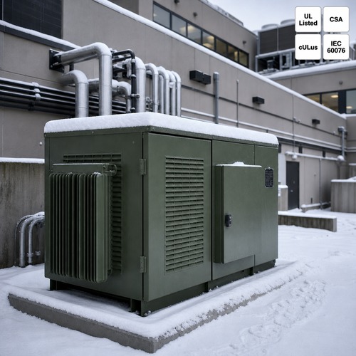
In the Ontario case the retained building load after boiler removal was 520 kVA. Total came to 927 kVA. The existing 750 kVA pad-mounted unit was already running near 98% on peak summer days, so reuse was not on the table. We specified 1,500 kVA, 13.8 kV delta to 480Y/277 V, 5.75% impedance, which is the next standard size and leaves roughly 35% headroom for a second phase of the same program.
Three numbers follow directly and each one changes downstream hardware. Primary current is 62.8 A. Secondary full-load current is 1,804 A. Available secondary fault current at the terminals is about 31 kA, and that figure decides whether the switchgear is ordered at 42 kA or 65 kA. It is also the figure contractors most often forget to request.
One caution on loading. A dry type transformer does not carry sustained overload the way an oil-filled unit does. IEEE C57.12.01 bases dry-type ratings on 30°C average and 40°C maximum ambient, and a rooftop enclosure in July sits well above that. Running a dry-type unit at 100% of nameplate inside a 50°C enclosure is a service-life decision disguised as a conservative one.
Inrush and Voltage Dip: Where Retrofits Usually Fail
Motor-starting dip across a transformer is approximately starting kVA divided by transformer kVA, multiplied by percent impedance. A 90 kW compressor with 140 A rated-load current and 6x locked-rotor current draws about 840 A at 480 V, which is 698 kVA of starting demand. Across a 1,500 kVA unit at 5.75% impedance that works out to roughly 2.7% dip, comfortably inside the 10% most utilities allow at the service point.
Shrink the transformer to 1,000 kVA and the same compressor produces 4.0% dip. Now put two compressors on the same staging command and the dip doubles for a fraction of a second, which is the condition that trips VFDs and resets controls. Cheap retrofit sequences do exactly this, because staging logic is written by the mechanical contractor and reviewed by nobody on the electrical side.
Inrush current at energization is a separate and larger event. A cold 1,500 kVA unit can draw 8 to 12 times rated current for the first 0.1 second, which at 480 V means 14,000 to 21,000 A. Leave the main breaker's instantaneous setting at the factory default and commissioning day opens with a nuisance trip, followed by an argument about whether the transformer is defective.
This is the part of the package buyers rarely see in a quotation. Every unit we ship into a retrofit leaves with a calculated inrush envelope attached to the routine test report, so the contractor can set short-time delay or specify point-on-wave closing before the truck arrives. On a Vermont school project the electrical specification listed locked-rotor amps for the compressors, but the submitted cut sheets quoted rated-load amps only. Submittal review caught the mismatch three weeks before delivery instead of at 6 a.m. on a January startup.
Harmonics From Inverter Compressors and What They Do to the Winding
Inverter-driven scroll and screw compressors do not behave like across-the-line motors. Their front ends draw non-sinusoidal current, typically 25% to 40% total harmonic current distortion at part load, and that spectrum lands in the winding as additional eddy-current loss and localized heating. A dry type transformer selected on kVA alone will run hotter than its nameplate suggests at exactly the hours when the plant is at 30% capacity.
There are two workable responses. Specify a K-rated unit, K-4 where a handful of drives are present and K-13 where VRF outdoor units or large VFD packs dominate, or derate the conventional unit using the harmonic loss factor method. Both are legitimate; ignoring the question is not, particularly on VRF systems where twenty small inverter units add their distortion at the same distribution point.
The secondary effect is leading power factor at light load. DC-link capacitors push current ahead of voltage when the plant idles at 20% on a mild day, so a transformer for heat pump electrification specified at 0.93 lagging now operates at 0.85 leading. Nothing fails immediately, but utility metering, capacitor banks and generator paralleling controls start behaving strangely. Tell the utility engineer before they discover it on a meter reading.
Cold Climate, Backup Heat and the Staging Problem
Below -12°C, standard air-source units deliver 55% to 65% of rated capacity. Cold-climate units hold 70% to 80% and keep COP near 1.8. Whatever the gap is, resistance heat fills it, and resistance heat arrives as load steps. A 120 kW backup bank staged in four 30 kW steps adds 36 A per step at 480 V. Individually that is nothing. All four energizing on one call is a 120 kW step change in under a second, and a transformer sized at exactly the calculated load has no answer for it.
Defrost is the hidden peak. Reverse-cycle defrost pulls heat out of the building loop while the compressors keep running, and a plant with eight modules can defrost in sequence on a humid 2°C morning. Design for the coincident defrost case, not the steady-state capacity table, and put the inrush current of restarts into the same calculation.
Enclosure and ambient deserve more attention than cold-climate specifications usually give them. Condensation on a de-energized dry-type winding at -25°C, followed by a fast morning load ramp, is a genuine failure path; space heaters and a thermostat that actually functions are not optional extras. For oil-filled pad-mounts in the same climate, fluid pour point and cold-start viscosity belong in the specification, not in a footnote.
From Spec to Shipment: What We Build and What We Test
Ryan Electric is a UL listed transformer supplier building 1,500 kVA class units like this one in a 120,000 m² facility in Jiangsu with 180+ sets of production and test equipment and 37 patents. As an Eaton joint venture partner since 2023, we work to the same loss and impedance discipline the larger North American OEMs apply, and we publish routine test data instead of summarizing it.
Every unit runs the IEEE C57.12.90 routine sequence: winding resistance, ratio, polarity, no-load loss, load loss, impedance, applied voltage and induced voltage, plus a temperature-rise type test on the design. Impedance is held to ±7.5% of the specified value, which matters when a utility studies fault current before approving a service upgrade. That study is also the reason a dry type transformer quotation should state impedance explicitly rather than leave it to the factory default.
Certification is where a UL listed transformer supplier either has the documents or does not. UL 1561 for dry-type general-purpose units, CSA C22.2 No. 66 for Canada, cULus where both markets apply. On the Ontario campus the utility wanted the CSA mark legible on the nameplate and a test report traceable to the serial number. Both were in the shipping envelope, and the inspection passed on the first visit.
Delivery ran 16 weeks from approved drawings, with the owner's third-party inspector witnessing routine tests. After our commissioning note, the staged resistance heat was rewired to two-step control and the measured service dip on backup engagement dropped from 3.9% to 1.8%. That change cost a contactor and two hours of an electrician's time.
Next Step
If you are converting a gas-heated building, send four things: the design-day heating load with the capacity table behind it, compressor rated-load and locked-rotor current, the retained building load, and the enclosure ambient. We return a sizing sheet with calculated kVA, predicted voltage dip, available fault current and a K-factor recommendation, usually within two working days.
Ask for the UL listed transformer supplier document set at the same time: routine test report, UL or CSA listing reference, and an impedance tolerance statement. Utility reviewers ask for those three, and having them ready shortens a service upgrade approval far more than any price negotiation will.
About the Author — This article was written by the transformer engineering team at Ryan Electric, a UL/CSA-certified manufacturer and Eaton joint venture partner based in Jiangsu, China, supplying dry-type, oil-immersed and pad-mounted transformers to data center, energy storage, renewable, healthcare and utility projects across North America, the Middle East, Southeast Asia and Africa.
Table of Contents
- Electrification Retrofits Break Transformer Assumptions
- The Load Math: What Heat Pumps Actually Ask From the Service
- Sizing the Transformer for Heat Pump Electrification
- Inrush and Voltage Dip: Where Retrofits Usually Fail
- Harmonics From Inverter Compressors and What They Do to the Winding
- Cold Climate, Backup Heat and the Staging Problem
- From Spec to Shipment: What We Build and What We Test
- Next Step