
 EN
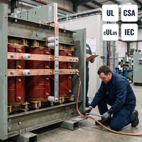
An inspector stops the sign-off on a new 1,000 kVA unit because the neutral is landed on the enclosure ground bar, the green bonding screw is still in its factory position, and a bare copper conductor runs from X0 to the building steel. Each detail looks reasonable on its own. Together they break transformer grounding for a separately derived system, and they leave a parallel neutral path that will carry current on the grounding system for the life of the building.
We build these units, and we sit in on enough commissioning walks to know that grounding is where good installers lose the most time. The transformer arrives correct. The bond is made in the wrong place, or made twice, and suddenly a mechanical room has circulating current, nuisance GFCI trips and a red tag. This article walks through what NEC 250.30 actually asks for, where the arguments start, and what to check before the utility energizes.
What Makes a Transformer a Separately Derived System
A separately derived system is a premises wiring system whose power comes from a source with no direct electrical connection to the supply conductors, other than through magnetic coupling. A delta-wye transformer feeding a panelboard with a neutral is the textbook case. The 480 V delta primary is connected to the utility; the 208Y/120 V secondary is a new source. The neutral that appears at X0 does not exist upstream — the transformer made it.
Take a 1,000 kVA, 480 V delta to 208Y/120 V wye unit at 5.75% impedance. Primary current is 1,203 A, secondary current is 2,776 A, and the neutral is a genuine current-carrying conductor on any circuit with line-to-neutral loads. That is why the grounding rules for this transformer are different from the ones for a delta-delta unit with no neutral: there is a conductor that must be bonded to earth, at exactly one point.
Article 100 of the NFPA 70, National Electrical Code defines the term, and 250.20(D) requires the system to be grounded where it can be grounded. Section 250.26 then fixes which conductor is the grounded one. For a wye secondary, that is the neutral. For a delta secondary with a grounded phase, it is a phase conductor, and every downstream bonding decision shifts with it.
Where the System Bonding Jumper Belongs
NEC 250.30(A)(1) gives two legal locations for the system bonding jumper: at the transformer, or at the first system disconnecting means. One location, not both. If the bond is made inside the transformer, the neutral terminal must be insulated from the enclosure and the bonding jumper is the only connection between X0 and the frame. If the bond is made at the first disconnect, the neutral must stay isolated all the way there and the jumper is installed in that enclosure.
The failure mode is almost always a factory default that nobody removed. Dry-type units ship with a bonding provision on the neutral block, and plenty of crews land the neutral and leave the tie in place while the electrician at the panel also bonds neutral to ground. Now the grounding system is a parallel neutral. Current divides between the neutral and every conduit, raceway and building steel path it can find, which is exactly what 250.6 prohibits as objectionable current.
Sizing matters, but location matters more. The jumper is sized from the derived phase conductors, and on a 1,000 kVA unit with a 2,776 A secondary that is a serious piece of copper. What we tell contractors is simple: decide the bonding point on the drawing, mark it on the transformer, and write it on the panel schedule. A bond that exists in two places is worse than a bond that is documented in one.
Sizing the Grounding Electrode Conductor
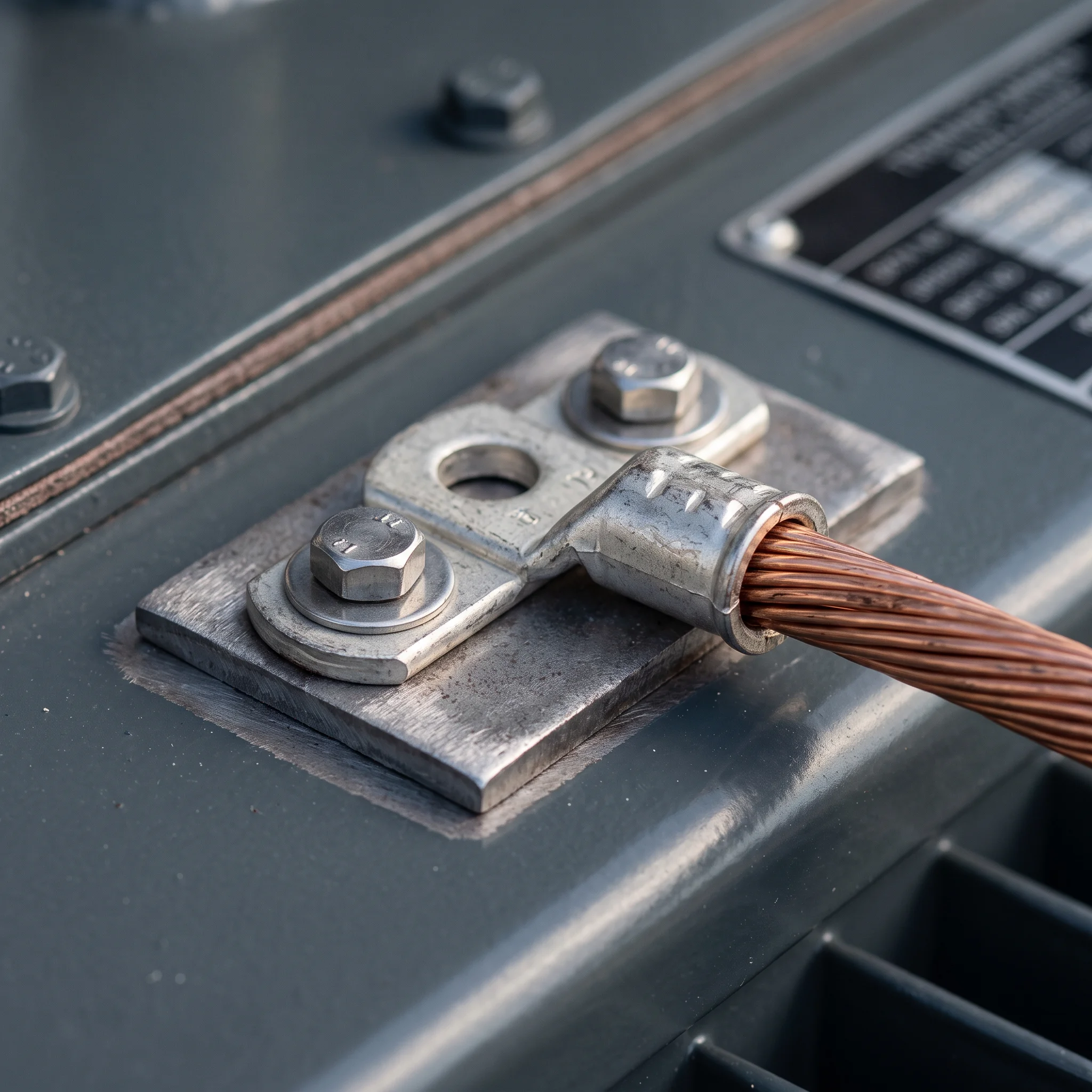
NEC 250.30(A)(2) sends you to Table 250.66 for the grounding electrode conductor at a separately derived system. The conductor is sized from the area of the largest derived ungrounded conductor, not from the transformer kVA and not from the overcurrent device. Table 250.66 also caps the requirement: above 1,100 kcmil of derived conductor, the grounding electrode conductor does not have to exceed 3/0 AWG copper or 4/0 AWG aluminum.
For that 1,000 kVA example, the secondary needs multiple parallel runs, so the largest single derived conductor is well past the 1,100 kcmil threshold — 3/0 AWG copper is the code answer. We see two opposite mistakes on the same day of a commissioning walk: a crew pulling 4/0 because the transformer is large, and a crew pulling 2 AWG because the transformer is only 208 V on the secondary. Neither reading comes from the table.
The other half of 250.30(A)(2) is where the conductor terminates. It has to reach the grounding electrode system described in 250.50 — metal underground water pipe, structural steel, a concrete-encased electrode, a ground ring, or rods. A single driven rod at the pad is not a substitute for bonding to building steel. We have watched designs add a rod for good measure and still fail, because the rod was the only electrode and the steel was never bonded.
The Ground Fault Return Path Is the Real Objective
Transformer grounding is not primarily about earth resistance. It is about giving a line-to-ground fault a low-impedance metallic path back to the source so the overcurrent device opens. NEC 250.4(A)(5) calls this the effective ground-fault current path.
Numbers make the stake clear. That 1,000 kVA unit at 5.75% impedance can deliver roughly 48 kA into a bolted three-phase fault at its secondary terminals, which any properly sized breaker clears instantly. A 120 V arcing ground fault is a different animal: current is limited by arc impedance and by the return path, and it can sit in a range that a 2,000 A frame never sees as a fault. If the return path is broken or duplicated, that fault burns until something else fails.
That is why we ask for the one-line and the grounding detail before releasing a custom unit. Two projects with identical nameplates can need different neutral arrangements, and the difference lives on the drawing, not in the transformer.
Transformer Grounding Mistakes We See on Site
A 1,500 kVA, 480 V to 208Y/120 V unit went into a mechanical room in Texas last year. The crew bonded X0 to the enclosure inside the transformer, then bonded neutral to ground again at the first panel 40 ft away, and ran the grounding electrode conductor from the transformer frame to a lone rod beside the pad. Building steel was 15 ft away and untouched. On startup, a clamp meter read 4.1 A on the grounding electrode conductor with the building at about 30% load.
Nothing failed that day, which is the problem. That current had been riding the grounding system, the conduit couplings and the steel for weeks. The fix took a morning: remove the downstream bond, separate neutral and ground bars in the panel, run a properly sized grounding electrode conductor to the building steel, and re-terminate the frame connection on bare metal because the pad had been painted after assembly.
The other repeat offender in transformer grounding is hardware. A lug torqued by feel on a painted surface reads fine on a continuity meter and fails a thermal scan at full load. Listed lugs carry a torque label for a reason, and star washers do not replace bare metal.
What a Custom Three Phase Transformer Should Arrive With
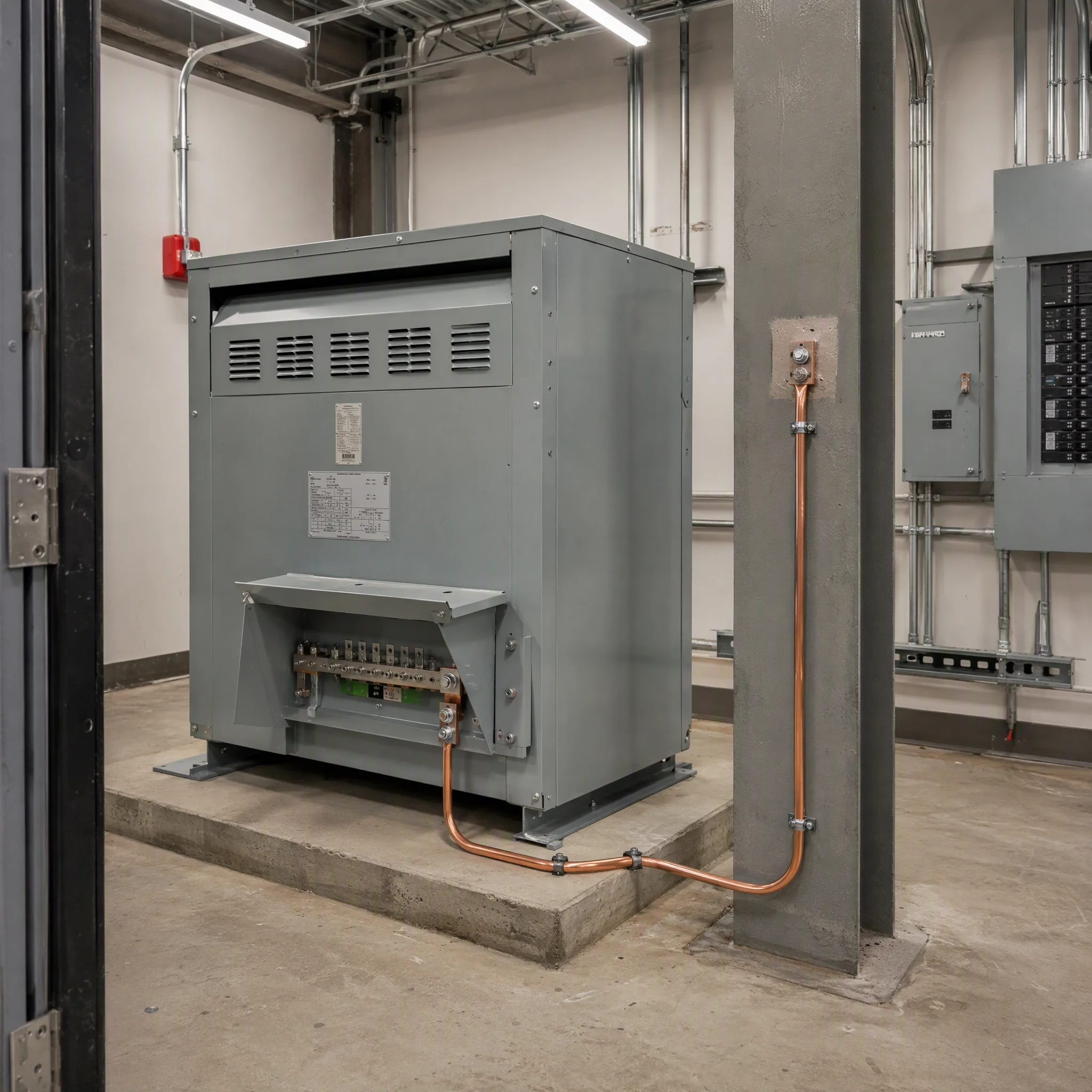
The transformer cannot enforce the code, but it can make the correct installation obvious. On a custom three phase transformer with a wye secondary we provide a clearly marked X0 pad, a separate enclosure ground pad with paint removed at the factory, a nameplate to IEEE C57.12.00, and a connection diagram that states whether the neutral is factory bonded. If the specifier wants the bond at the first disconnect, the unit ships with the neutral isolated and the bonding provision left open.
Documentation is part of the product. Every unit leaves with routine test data — ratio, winding resistance, insulation resistance, applied and induced potential — plus the UL or cULus listing mark and a CSA mark where the project requires it. As a UL listed transformer supplier working to IEEE and IEC test regimes, we have had inspectors ask for the connection diagram at the pad more often than for the test report. Ryan Electric has manufactured in a 120,000 m² plant with 37 patents since 2007, and since 2023 has operated a joint venture partnership with Eaton, which is why the drawing package for a North American job now gets reviewed against both our own checklist and a partner audit.
A Pre-Energization Transformer Grounding Checklist
Print this and take it to the walk. Every line is something an inspector can and will check, and every line has caused a re-inspection we know of.
| Item | What to verify | Reference |
| Bonding point | System bonding jumper installed at the transformer OR at the first disconnect, never both | NEC 250.30(A)(1) |
| Neutral isolation | Neutral block insulated from enclosure where the bond is downstream; factory tie removed | NEC 250.30(A)(1) |
| GEC sizing | Sized from largest derived ungrounded conductor; 3/0 Cu cap above 1,100 kcmil | NEC 250.66 |
| Electrode system | GEC terminates on the grounding electrode system, not on a lone rod when steel is present | NEC 250.50 |
| Panel wiring | Neutral and ground bars separated in the first panel downstream of the bond | NEC 250.24(A)(5) intent |
| Hardware | Paint removed at ground pads, listed lugs torqued to the label, no ground path through removable covers | Manufacturer listing |
| Continuity | End-to-end continuity from X0 bus to farthest equipment ground, measured not assumed | Commissioning test |
Grounding decisions are cheap at the drawing stage and expensive at the walk-through. The question to settle early is not which standard applies — 250.30 is clear — but where the single bond lives on this particular project, and who owns it: the transformer manufacturer, the switchgear builder, or the electrical contractor. Put that answer on the one-line, and the field work becomes mechanical.
If you are specifying a wye-secondary unit and want the neutral arrangement, ground pad and documentation matched to your grounding detail, send the one-line and the required listing marks with your inquiry. We will return a drawing for review before the winding is scheduled, which is a far better place to argue about a bonding jumper than a mechanical room with the utility waiting.
About the Author
This article was prepared by the Application Engineering Team at Ryan Electric, a transformer manufacturer in China supplying oil immersed, dry type and pad mounted transformers to North America, the Middle East, Southeast Asia and Africa since 2007. The team handles grounding and neutral arrangement reviews, connection diagrams, routine and type test documentation, and UL / cULus / CSA / IEEE / IEC certification packages for utility, data center and industrial projects. Drawing reviews and grounding questions can be sent through the contact form at www.ryantransformers.com. Last reviewed: October 2026.
Disclosure: Ryan Electric manufactures and sells the transformers discussed in this article. Code references (NEC 250.30, 250.50, 250.66, 250.6, 250.4) are summarised for engineering discussion only and should be verified against the edition of NFPA 70 adopted in your jurisdiction before installation.
Table of Contents
- What Makes a Transformer a Separately Derived System
- Where the System Bonding Jumper Belongs
- Sizing the Grounding Electrode Conductor
- The Ground Fault Return Path Is the Real Objective
- Transformer Grounding Mistakes We See on Site
- What a Custom Three Phase Transformer Should Arrive With
- A Pre-Energization Transformer Grounding Checklist