
 EN
EN
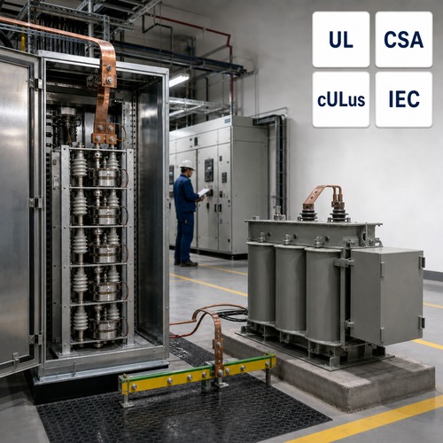
The switchgear schedule specified high-resistance grounding at 5 A with a 10-second resistor. The contractor installed exactly that. Nobody measured the system charging current, which on the shielded 5 kV cable, surge arresters and drive input filters in that plant came to roughly 6.8 A. On the first phase-to-ground fault the resistor carried the full capacitive current, the sensing relay never saw a rise, and the plant ran for two days with a grounded phase. The second fault, on a different phase, turned a nuisance into a phase-to-phase arc flash. Everything had been built to the drawing. The grounding scheme was still wrong.
Transformer neutral grounding is the design decision that fixes how much current flows when insulation fails, whether protection trips or merely alarms, and how much of that current the transformer, cables and switchgear have to survive. It is made once, at design stage, and it usually occupies a single line of a specification.
Four methods cover nearly every industrial, utility and data centre system: solid grounding, low-resistance grounding, high-resistance grounding, and grounding through a zig-zag or wye-delta grounding transformer. Each one answers a different question, and the right answer depends on what you want the system to do on the first ground fault.
What Transformer Neutral Grounding Decides
A ground fault completes a circuit between a phase conductor and earth. The current that flows is set by the impedance of the return path, and that return path is created by the connection between the system neutral and the grounding electrode system. Change the connection and you change the fault current, the speed of detection, and the amount of damage the fault does while it is being cleared.
Two references are worth naming in the specification. IEEE Std 3003.1-2019 covers system grounding for industrial and commercial power systems and is the modern successor to the Green Book family; IEEE Std C62.92.1-2016 covers neutral grounding for utility systems rated above 1,000 V. Both are built around the same trade-off: ground-fault current has to be high enough to be detected reliably, and low enough not to destroy equipment.
The table below condenses the four methods.
| Method | Typical fault current | Detection philosophy | Where it fits |
| Solid grounding | Up to the bolted three-phase value | Instantaneous overcurrent, trips | 480 V and below, LV distribution |
| Low resistance (LRG) | 100 A - 1,000 A, commonly 200 A - 400 A | Overcurrent relays, selective coordination | MV industrial distribution needing selective tripping |
| High resistance (HRG) | 5 A - 25 A | Sensitive relay, alarm first | Drive-heavy plants, continuous process, data centres |
| Zig-zag grounding transformer | Set by the resistor or transformer design | Sensitive relay | Delta systems, no accessible neutral |
Solid Grounding: The Lowest Cost and the Highest Fault Current
On a solidly grounded system the neutral is bonded directly to the grounding electrode system. Nothing limits the current, so a phase-to-ground fault can approach the bolted three-phase value available at that point - tens of kiloamps on a 2,000 kVA unit at 480 V. That is not a design flaw; it is the point. The fault is large, every protective device sees it, and it is cleared in cycles.
The bill arrives elsewhere. Bus bracing, breaker interrupting ratings and the incident-energy calculation in the arc-flash study all scale with that current. Solid grounding is still the practical choice for most 480 V systems, because the phase-to-ground voltage stays at 277 V and insulation and surge-arrester duties stay modest. Where it stops making sense is at medium voltage, where the same logic produces fault currents the transformer, cables and switchgear would rather not see.
One consequence surprises people. On a solidly grounded system most faults begin as a single phase-to-ground event and are cleared before they escalate. On an ungrounded or high-resistance grounded system, the first fault frequently is not cleared at all.
Resistance Grounding: Low Resistance versus High Resistance
Inserting a resistor between the neutral and earth turns a design philosophy into a number. Low-resistance grounding typically limits the current to a few hundred amps - 200 A to 400 A is common at medium voltage - which is still enough for standard overcurrent relays to see and to coordinate. That is why LRG is used where the plant wants a faulted feeder to trip selectively instead of tripping the main.
High-resistance grounding goes much further and limits ground-fault current to 5 A, 10 A or 25 A. At those levels the fault is normally an alarm rather than a trip, and the plant keeps running while maintenance locates it. Drive-heavy industrial systems, continuous-process plants that cannot absorb a trip, and data centre medium-voltage distribution all lean on this approach. The transformer and cables no longer have to survive a multi-kiloamp event, and the arc-flash exposure from a ground fault falls with the current.
Here is the part most buyers miss. A high-resistance grounded system only works if the resistor's let-through current is above the system charging current. The charging current of shielded cable, surge arresters and drive input filters is real current, and on a ground fault it flows through the resistor and the fault together. If the resistor current is smaller than that, the relay cannot distinguish a fault from normal capacitive current - which is exactly what happened in the example that opened this article. The correct sequence is to measure the capacitive current of the actual installation, select the resistor current above it with margin, and only then set the time rating.
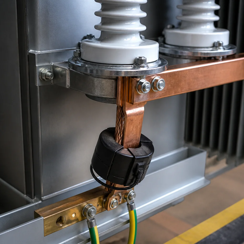
Zig-Zag Grounding Transformers: A Neutral Where There Is None
Everything above assumes a neutral you can connect a resistor to. A delta-connected source, or a transformer whose secondary neutral is not brought out, gives you no such point. A zig-zag unit solves that. Its windings present a low impedance to zero-sequence current, so they create a deliberate return path for ground-fault current, while presenting a high impedance to positive- and negative-sequence current, so the unit carries almost no load current in normal operation. A wye-delta unit does the same job with a different winding arrangement.
That behaviour is why a grounding transformer is specified from a completely different datasheet than a load transformer. The numbers to agree are the short-time neutral current and its duration - 10 seconds and 1 minute are the common ratings - plus a continuous neutral current capability for the unbalance that normal operation produces, which on a zig-zag unit is typically a few percent of the short-time figure. Specify it on the short-time number alone and a persistent unbalance will overheat it. Specify it like a load transformer and you buy copper you will never use.
On drive-heavy systems the zig-zag unit is usually paired with a resistor. The resistor sets the let-through current; the transformer supplies the neutral the resistor needs.
Sizing the Resistor: Four Numbers That Decide Whether It Works
A neutral grounding resistor is a short-time device with a small number of critical ratings. These four decide whether the scheme works in service:
- Measured capacitive current. Measure it on the real installation, at the real voltage. Table values are a starting point, not an answer.
- Let-through current. 5 A, 10 A or 25 A for high-resistance grounding; 200 A to 400 A for low-resistance grounding. In both cases it must sit above the measured capacitive current, with margin.
- Time rating. Ten seconds and one minute are typical. A 400 A, 10-second resistor on a 13.8 kV system dissipates roughly 3.2 MW while it carries the fault - about 32 MJ of energy in ten seconds. A fault left on the system will destroy it.
- Voltage and insulation rating. During a ground fault the resistor holds the full system line-to-neutral voltage, continuously, for the duration of the event.
Two more items belong in the same conversation but not on the resistor datasheet: the detection scheme - what the relay does with the current it sees, and whether it alarms or trips - and, for low-resistance grounding, whether the coordination study still holds once the current is limited.
How Ryan Electric Supports Grounding Design on Custom Orders
Grounding design starts at the transformer, because the winding configuration decides whether a neutral exists at all. On a custom three-phase transformer with a wye secondary we bring the neutral out on an insulated bushing rated for the ground-fault duty the study specifies, and we supply the winding configuration and vector group data the grounding and coordination studies need. Where a customer's scheme calls for resistance or zig-zag grounding, we confirm the neutral arrangement at quotation stage rather than at the factory acceptance test. It is a fifteen-minute conversation up front and a rework order if it is missed.
We build in a 120,000 square metre facility with more than 180 sets of production and test equipment and 37 patents, and we hold UL, CSA, IEEE, DEKRA, CNAS and CE certification coverage. Since 2023 Ryan Electric has operated as an official joint venture partner of Eaton. The routine test report that ships with each unit carries the winding resistance and ratio data a commissioning team needs to confirm the neutral and grounding connections on site.
Send the Grounding Scheme With the Transformer RFQ
Send us the one-line diagram, the grounding method, the neutral current and duration you are designing to, and the transformer rating. Our engineering team will come back with a transformer neutral grounding arrangement that matches the study - neutral bushing included - so the commissioning engineer confirms a design instead of discovering one. Getting the groundwork right at quotation costs nothing. Discovering it after the first ground fault costs an outage.
About the Author: This article was written by the engineering team at Ryan Electric (Jiangsu Ryan Transformers), a manufacturer of cast resin, oil-immersed and pad-mounted transformers serving utility, data centre, renewable generation and industrial customers since 2007. The team works daily with IEEE C57 and IEC 60076 requirements and supports developers and EPC contractors through specification, factory testing and site commissioning.
Table of Contents
- What Transformer Neutral Grounding Decides
- Solid Grounding: The Lowest Cost and the Highest Fault Current
- Resistance Grounding: Low Resistance versus High Resistance
- Zig-Zag Grounding Transformers: A Neutral Where There Is None
- Sizing the Resistor: Four Numbers That Decide Whether It Works
- How Ryan Electric Supports Grounding Design on Custom Orders
- Send the Grounding Scheme With the Transformer RFQ