
 EN
EN
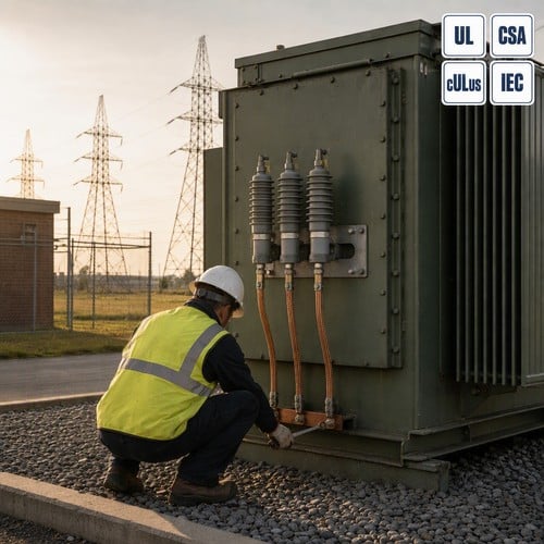
A utility foreman in southern Luzon emailed us a photograph last August of an installation that looked perfectly normal on the day it was signed off: a 13.8 kV pad-mounted transformer, a new polymer arrester on its bracket, fresh paint. Two details were not in the original spec. Four feet of coiled lead wire between the arrester terminal and the tank. And a ground conductor routed back through the mounting bracket instead of straight down to the ground pad. Three weeks later lightning hit the feeder. The arrester survived without a mark on it. The primary winding did not.
What a Surge Arrester Does — and What It Cannot Do
A modern transformer surge protection scheme is built around a gapless metal-oxide varistor. Below its reference voltage the varistor behaves like an open circuit and draws microamps. Above it, the resistance collapses, the arrester shunts the surge current to ground, and it returns to a high-impedance state well before the next half cycle. IEEE C62.11-2020 defines the device itself, covering metal-oxide arresters for 48 to 62 Hz circuits above 1,000 V that limit lightning and switching surges by passing discharge current and then automatically limiting the flow of system power current. It is an active standard, published in September 2020.
The arrester does not absorb a surge. It clamps it. What the winding actually experiences is the arrester’s discharge voltage plus the voltage the surge develops across the lead wire running from the arrester terminal to the point it is protecting. Both terms are real. Only the second one can still be changed with a wrench on the day of installation.
An arrester that was perfectly selected can still be a badly applied arrester. The selection and the connection are two different jobs, and buyers usually delegate only one of them.
Transformer Surge Protection Starts with MCOV, Not with Rated kV
Most of the RFQs that reach our engineering desk specify an arrester by rated voltage — “a 10 kV arrester”, “an 18 kV arrester”. That number is a duty-cycle rating, and on its own it says almost nothing about whether the unit belongs on your system. The number that decides the application is MCOV: the maximum continuous operating voltage, the highest RMS voltage the arrester can hold across its terminals indefinitely without overheating.
MCOV is set by the system grounding, not by the transformer. On an effectively grounded system the arrester sees line-to-ground voltage in normal operation, so the requirement is the maximum line-to-ground voltage itself — 7.65 kV on a 12.47 kV multi-grounded system. On an ungrounded or impedance-grounded system, a phase-to-ground fault lets the unfaulted phases approach full phase-to-phase voltage, so the rule becomes MCOV at or above 90 percent of maximum phase-to-phase voltage. Same transformer, same voltage class, two very different arresters.
| System line-to-line voltage (kV, nominal) | Arrester MCOV — effectively grounded (kV) | Arrester MCOV — impedance grounded or ungrounded (kV) |
| 4.16 | 2.55 | 5.10 |
| 12.47 | 7.65 | 15.30 |
| 13.80 | 8.40 | 15.30 |
| 24.94 | 15.30 | 29.00 |
| 34.50 | 22.00 | Not recommended |
Those figures come from the arrester application data published by Hubbell Power Systems, and they match what we see on North American distribution systems (Hubbell Catalog 70, Surge Arresters). The practical consequence is worth stating plainly. If a specification says “ungrounded system” but the system is actually four-wire multi-grounded, you buy roughly twice the MCOV you need — and you pay for that with a higher discharge voltage, which is precisely the number you were trying to keep low.
One further relationship is useful when you are reading a datasheet: the rated voltage of an arrester is generally about 1.25 times its MCOV. That is why a 10 kV rated distribution arrester carries an MCOV around 8.4 kV, and why both numbers move together when you change the grounding assumption on the same transformer.
Lead Length, Grounding, and the Protective Margin That Actually Counts
Here is the part most buyers miss. Every foot of lead wire between the arrester and the equipment it protects adds voltage to the insulation during a surge, because the current has to travel that distance and return. The IEEE application guide for metal-oxide arresters uses 1.6 kV per foot at 10 kA, and FM Approval Standard DS 5-11 for lightning and surge protection of electrical equipment uses the same figure.
| Arrester lead length (ft) | Voltage added at 10 kA (kV) | Share of a 95 kV BIL winding |
| 1 | 1.6 | 1.7% |
| 2 | 3.2 | 3.4% |
| 4 | 6.4 | 6.7% |
| 10 | 16.0 | 16.8% |
The protective margin is the arithmetic that ties all of this together. Take the winding BIL, subtract the arrester’s discharge voltage and the lead contribution, then divide by the BIL. On a 13.8 kV distribution transformer the standard primary insulation level is 95 kV BIL, and the recommended minimum protective margin is 20 percent. A 10 ft lead consumes 16 kV of that 95 kV — close to the entire recommended margin, before a single kV of arrester discharge voltage is counted against it.
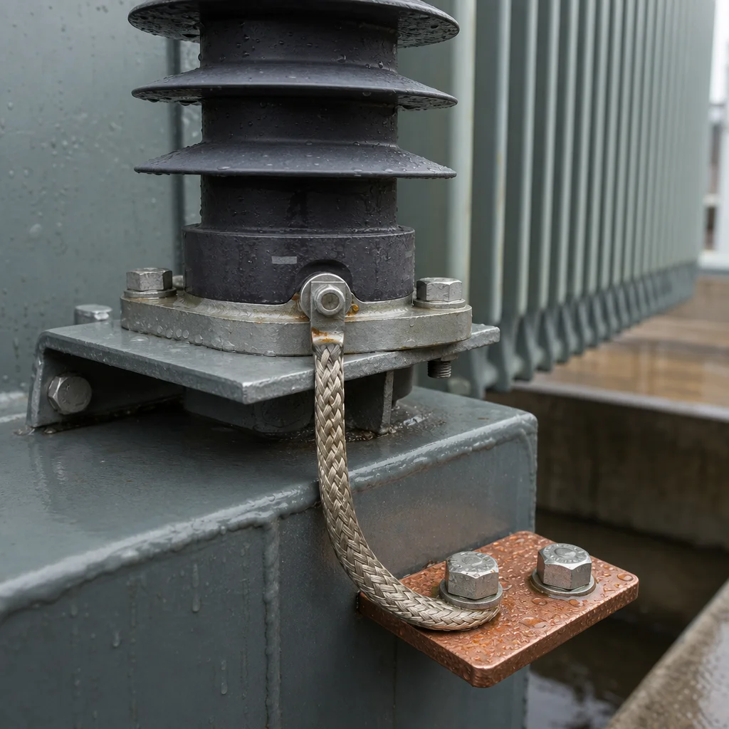
Grounding fails in the same quiet way. The ground lead should run short, straight and separate from the mounting bracket, landing on a dedicated pad bonded to the tank and to the station ground grid. Routing the ground path through bolted bracket hardware introduces a joint that corrodes, loosens and adds impedance at exactly the moment the surge arrives. NFPA 780, the Standard for the Installation of Lightning Protection Systems, is the current 2026 edition and is the reference most North American inspectors work from. Read it before you approve a layout, not after a failure.
Choosing the Right Arrester Class for the Transformer You Are Buying
Arresters are classified by the surge energy and fault current they are expected to survive, and the class should follow the criticality of whatever sits behind it — not the size of the purchase order.
| Arrester class | Typical application | Selection notes |
| Distribution | 12.47–34.5 kV distribution transformers, pad-mounted units, riser poles | 10 kA nominal discharge current. Normal duty suits lightly loaded rural feeders; heavy duty where the unit is exposed or the feeder is long. |
| Intermediate | Small substations, medium-voltage switchgear, transformers above 5 MVA | Higher energy capability than distribution class. Used where the protected equipment is expensive and the exposure is high. |
| Station | Transmission-class transformers and critical substations | Highest energy and fault-current withstand. Pressure-relief behaviour and grading requirements are explicit in IEEE C62.11. |
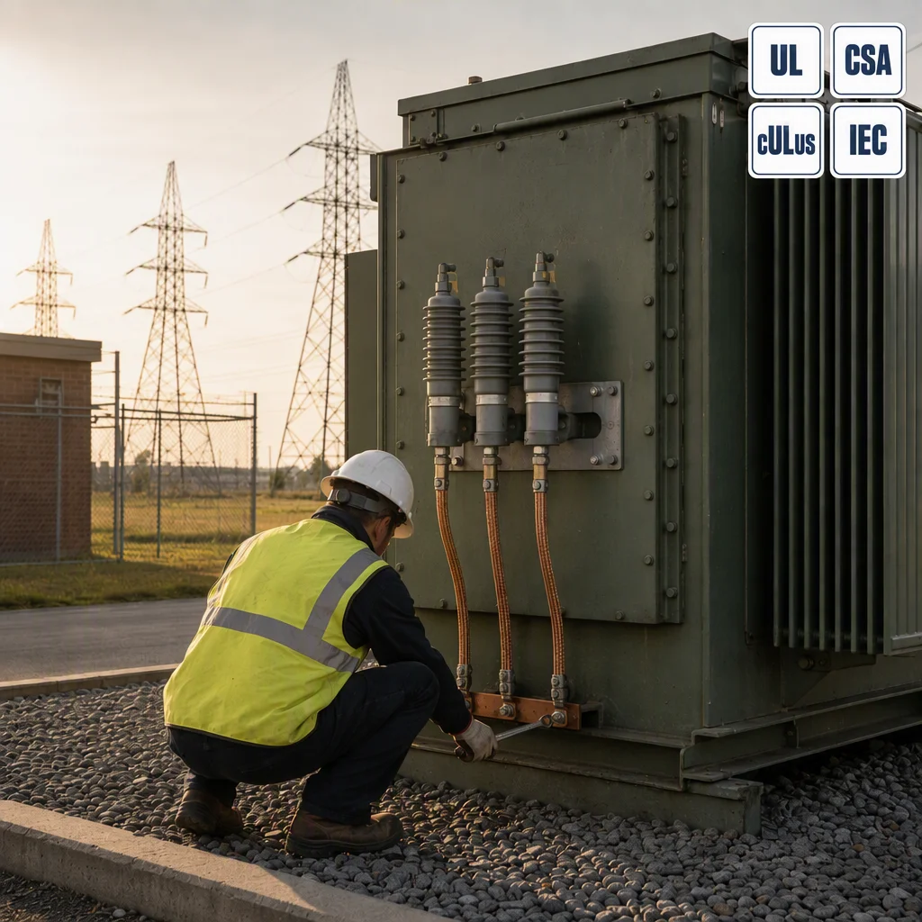
On pad-mounted transformers in North America the arrester is normally bolted to the tank with a dedicated bracket and cover, and the ground lead lands on a pad welded to the tank wall. That is not decoration. It is the shortest practical path from the arrester base to grounded steel, and it is the only path that keeps the lead contribution inside the range our engineers calculate at quotation stage.
Three Arrester Problems We See Repeatedly in the Field
We ask for photographs of the existing installation before we quote a replacement unit, and the same three patterns keep coming back.
- Coiled or looped lead wire. A crew holding 6 ft of lead and needing 18 in. of it will coil the remainder neatly along the tank. Every turn adds inductance and voltage. Shorten the lead; do not tidy it.
- Ground path through the mounting bracket. It is fast, and it is wrong. Bracket bolts are not a grounding conductor on the day of installation, and they will not become one after two winters in a coastal yard.
- Arrester sized from transformer kVA instead of system grounding. The kVA rating of the unit has no bearing on MCOV. The grounding configuration does, and it is a one-line answer on the drawing.
One further failure hides inside the first. A distribution arrester with an external disconnector will drop its lead if the arrester fails short, which is exactly what you want — but the disconnector needs an air gap that stays clear. We have opened cabinets where a single strand of wire, or an insect nest built over a season, had bridged that gap. The arrester was still there. It just was not protecting anything.
How We Build Surge Protection into Every Transformer Order
Ryan Electric has manufactured transformers since 2007, and since 2023 we have operated as a joint-venture partner of Eaton. In the Danyang plant — 120,000 square meters, more than 180 sets of production and test equipment, 37 patents — the dielectric test hall runs the routine tests a project specification calls for alongside the impulse tests on the designs that require them, and the BIL stamped on the nameplate is the level the design was qualified at.
When an order includes arresters, we size MCOV from the system grounding you give us, list the mounting bracket and cover in the bill of materials, and weld a ground pad so the installer has a direct landing point instead of a convenient bolt. On UL and CSA programmes the bracket, the ground pad and the tank bonding are reviewed as part of the assembly, not treated as field accessories.
What to Put in Your RFQ for Transformer Surge Protection
Four lines in an RFQ will save a revision later, and none of them takes more than a minute to find on the drawings.
- System grounding: effectively grounded, impedance grounded, ungrounded or delta — plus the maximum system voltage, not just the nominal.
- Required MCOV if you already have it, and the arrester class you intend to specify.
- Mounting method: tank bracket, cross-arm, inside the cabinet, or a switchgear cubicle.
- Achievable lead length in the actual layout, and where the ground pad will land.
Send the one-line diagram and the site plan with those four answers, and we will return the arrester selection, its discharge voltage, the lead contribution and the resulting protective margin in the quotation — so the discussion happens on paper, at your desk, instead of in a substation after a storm. Reach the application engineering team at [email protected], or open the product pages for oil-immersed transformers and pad-mounted transformers to request sizing support for a specific project.
About the Author
This article was prepared by the application engineering team at Ryan Electric (Jiangsu Ryan Electric Co., Ltd.), a transformer manufacturer working on distribution, power and renewable-energy projects for utility, data centre, industrial and infrastructure customers worldwide. Our engineers specify arrester selection, insulation coordination and grounding details on the same designs that run through our Danyang test hall. For questions on MCOV selection or protective margin on a specific project, write to [email protected].
Table of Contents
- What a Surge Arrester Does — and What It Cannot Do
- Transformer Surge Protection Starts with MCOV, Not with Rated kV
- Lead Length, Grounding, and the Protective Margin That Actually Counts
- Choosing the Right Arrester Class for the Transformer You Are Buying
- Three Arrester Problems We See Repeatedly in the Field
- How We Build Surge Protection into Every Transformer Order
- What to Put in Your RFQ for Transformer Surge Protection
- About the Author