
 EN
EN
Why a Water Plant Is Hard on a Transformer
The aeration blowers in one plant we quoted last year ran fine for nine months and then started tripping the same breaker every afternoon. The blowers were not the problem. Neither was the drive. The water treatment plant transformer had been ordered from the plant's running load — 1,250 kVA of pumps and blowers — with no allowance for the harmonic current the drives would push back into it, and no allowance for a restart with three 250 hp motors on the same bus.
Water and wastewater plants are among the least forgiving places in the world to put a transformer. The load is cycling, induction-motor driven, half of it behind variable frequency drives, and the air is humid, chlorinated or full of hydrogen sulfide. Get any of those three wrong and the failure shows up as nuisance tripping, a hot winding, or a rusted enclosure that fails an inspection in year two.
Load Characteristics That Decide the kVA Rating
Three characteristics of the duty drive the specification, and they pull in different directions.
- The load profile is bimodal. A treatment plant is not a factory running a steady process load. It runs a base load overnight, then sits at peak during the day, then restarts pumps after a wet-weather event when inflow doubles. Transformers sized on the annual average will be loaded well above the average for a large share of the year.
- Almost everything is a motor. Pumps, blowers, mixers, sludge scrapers, bar screens. Motors draw locked rotor current at start, and the transformer sees the voltage dip that comes with it — which the plant experiences as a soft start, a contactor chatter, or a PLC reboot.
- Half the load is non-linear. Aeration blowers, primary pumps and chemical dosing all run on drives. When a plant designed for constant-speed operation is converted to VFD control — which is most of the upgrade work we quote — the transformer stays the same size while the harmonic current grows.
Add chlorine, moisture and hydrogen sulfide to the equipment room, and a general-purpose transformer stops being the obvious answer. What follows is what we check before we put a kVA number on a water or wastewater project, and it applies whether the unit is a pad mounted transformer outdoors or a dry-type unit in the MCC room.
Sizing for Pump Starts: The Six-to-Seven Times Rule
Motor starting decides kVA far more often than continuous load does. A squirrel-cage induction motor draws roughly six to seven times its full-load current while the rotor is locked, and the only thing between that current and the plant's voltage is the transformer impedance and the upstream network. The plant experiences the result directly: lights dip, drives trip on undervoltage, and the restart sequence locks out.
The working rule in North American practice is to size so that the voltage dip during the start of the largest motor does not exceed 10 to 15 percent at the motor terminals. That figure is a design convention repeated across consultant and utility guidelines rather than a single standard requirement, and it is the number we ask for on the RFQ. Give us the motor schedule — horsepower, code letter, NEMA design letter, starting method — and the transformer impedance follows from the dip limit rather than from a catalogue page.
Two practical points decide whether the transient study matches the plant you actually build.
- Starting method changes the answer. Across-the-line starting on a 300 hp blower can rule out a standard 5.75% impedance unit for a small plant; a soft starter or a drive with a current limit often lets the same transformer pass. The starting method belongs on the transformer datasheet, not only in the motor schedule.
- The generator is part of the calculation. When a standby generator carries the plant during a loss of utility supply, the effective source impedance rises sharply, and a blower that starts cleanly on the utility may stall the generator. Plants required to run full treatment during an outage must size both machines to the same starting case.
If your plant is mid-design and the motor schedule is still being revised, send us the current horsepower list and the worst-case simultaneous-start combination. Our engineers will return a voltage-dip check on the two or three kVA steps that fit, so the transformer is ordered on the same assumptions as your transient study.
VFD Loads and VFD Harmonics: Where the Extra Heat Comes From
A six-pulse drive draws current in short pulses rather than as a sine wave, and that current contains harmonic components the transformer was never sized for. The losses they create are not proportional to the fundamental current they replace. Stray flux from harmonic content heats windings, core clamps, tank walls and the neutral, and on a transformer already loaded to 80% of nameplate the result appears first as elevated top-oil temperature and then as a thermal trip.
There are three ways to specify your way out of it, and they are not equally good.
- Derate a standard unit. The blunt instrument: oversize by 15 to 25 percent against the drive load and accept the extra no-load loss for the life of the plant. It works, and it is often the cheapest first cost.
- Specify a harmonic-rated unit. A K-rated or drive-duty design uses a core and winding built to carry the extra eddy and stray loss, with a neutral sized for triplen harmonics where single-phase loads are present. Ask for the loading basis in writing, because a K-rating quoted without a stated K-factor and load profile is a label, not a design.
- Fix the harmonics upstream. Line reactors, passive filters or an active filter reduce what reaches the transformer at all, and they are the right answer when the plant must report distortion at the point of common coupling. IEEE Std 519-2022 is the reference your utility will apply, and the practical target most North American utilities enforce is the 5% total voltage distortion limit the standard sets for systems up to 69 kV.
Whichever route you take, the distortion figure belongs in the specification. A VFD harmonics clause that says “comply with IEEE 519” and nothing else leaves the transformer supplier guessing whether they are buying extra copper or you are buying a filter.
Corrosive Air: H2S, Chlorine and the Enclosure Decision
The equipment room at a wastewater plant is a hostile environment, and it is hostile in a way that is easy to underestimate. Headworks buildings, wet wells and digester areas carry hydrogen sulfide, which attacks copper, silver and the solder on control wiring even at concentrations nobody can smell. Chlorination and hypochlorite rooms add a second corrosion path. Add near-saturated humidity and the mechanism is not a coating failure — it is a connection failure two or three years in.
Three specification decisions carry most of the risk.
- Enclosure rating. For process areas in a wastewater environment the working minimum in municipal electrical design guides is a NEMA 4X enclosure — corrosion-resistant, not merely watertight — rather than the NEMA 3R an ordinary outdoor distribution transformer would use. That means stainless steel or a properly coated enclosure, gasketed doors and corrosion-resistant hardware, not a painted sheet-metal box.
- Coating system. Coastal and chemical exposure is normally specified as an ISO 12944 corrosion category rather than as a paint colour, with C5-M as the reference for high-corrosion, marine-grade service. When we build for that class the coating is documented with a salt-spray test on the coating build-up, and the finish schedule is part of the order rather than a factory default.
- Liquid preservation and access. On oil-immersed units, the oil preservation system and the sealing of the tank determine whether moisture migrates in over five years, and the placement of the sampling valve determines whether the maintenance team can take a sample without opening the enclosure. Ask where the valve is; if the answer is “inside, behind the door”, expect that sample never to be taken.
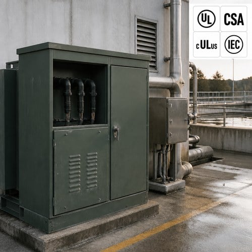
Outdoor placement for a pad mounted transformer solves the room problem but not the corrosion problem. A pad-mounted unit at a lift station sits in the same chlorinated, humid air as the pumps it feeds, so enclosure finish and gasket quality matter more than the location does.
Redundancy and Standby Power: The Configuration Question
Treatment plants are usually required to keep treating during a utility outage, and that requirement lands on the transformer arrangement as much as on the generator.
The common configuration is a main-tie-main double-ended arrangement with a normally open tie: two transformers, two switchboards, one tie breaker. Each transformer carries its own half of the plant, and the tie allows either transformer to carry essential loads if the other is out of service. The trade-off is impedance. Paralleled or tie-closed operation requires matched impedance and matched tap positions, or the two units will not share load the way the single-line diagram assumes. That is why we ask for the impedance band before quoting a pair rather than after.
Where a single transformer feeds the plant, the standby case usually looks like this: a generator at the service entrance, a transfer switch, and a decision about which loads are allowed to restart automatically. Blowers and drives are the problem. Large drives with a long ramp are easier on the generator than a direct-on-line restart, and a transformer specified with a low impedance for the utility case may make the generator case worse. Both cases have to be checked against the same motor schedule.
What to Put in the Specification
The specification items that decide whether the delivered unit matches the design intent:
| Specification item | What to state | What to ask |
| Motor schedule | Locked rotor kVA, code letter, NEMA design letter, starting method | Ask for the voltage dip limit: 10–15% is the working convention in North American practice |
| Simultaneous starts | The worst-case combination the plant will actually run | Post a wet-weather restart — three blowers plus a sludge pump is a different transformer than one pump at a time |
| Drive load | Total VFD horsepower and whether a filter or reactor is supplied | State the distortion target at the point of common coupling; IEEE Std 519-2022 is the reference your utility will use |
| Impedance band | Percent impedance and tolerance, taken from the transient study | Needed for the starting case and, on a double-ended arrangement, for load sharing |
| Enclosure and finish | NEMA 4X for process areas; ISO 12944 corrosion category | Name the category (C5-M for high-corrosion marine grade) instead of describing a paint colour |
| Standby configuration | Main-tie-main, generator-backed, or single-ended | The generator case sets a different impedance requirement than the utility case |
| Test scope | Routine tests on every unit; type tests on the design; partial discharge on dry type | Ask which test standard is used and whether listing agency witnessing is included |
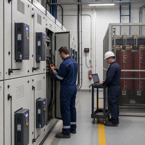
On testing, the split is worth stating explicitly. Routine tests run on every unit and follow the test code for the construction: IEEE C57.12.90 for liquid-immersed units in North America, and the general requirements in IEC 60076-1 for IEC projects, with dry-type designs following IEC 60076-11. Type tests — temperature rise, impulse and short-circuit withstand — belong to the design and should be traceable to the unit being supplied. Where the plant is converting to drives, ask for the harmonic loss check in writing, because that is the calculation that decides whether the unit runs cool or runs hot.
How We Build for Water and Wastewater Projects
Ryan Electric has manufactured transformers since 2007 at a 120,000 m² plant in Jiangsu with more than 180 sets of production and test equipment and 37 patents, and since 2023 we have operated as an official joint-venture partner of Eaton. Units ship with UL, CSA, IEEE, DEKRA, CNAS and CE credentials as the destination market requires, which matters on municipal work where the inspector reads the nameplate before anything is energized. Where a project is listed, the testing is witnessed through the listing agency rather than signed off in-house — for example through UL Solutions for North American listings.
The engineering difference on water projects is what we ask before quoting. Motor schedule with code letters, starting method, simultaneous-start case, drive horsepower and whether a filter is being supplied, enclosure classification for the process area, corrosion category, and the standby configuration. When those arrive together, the pad mounted transformer or dry-type unit that comes back is sized to the plant's operating case rather than to a total connected horsepower figure.
Send us the motor schedule, the site exposure and the enclosure requirement for your plant or lift station, and our engineers will return a sizing check against the starting case and the harmonic load, with the coating system and test scope listed line by line. Technical reply within 48 hours.
About the Author: This guide was prepared by the engineering and export team at Jiangsu Ryan Electric Co., Ltd., a transformer manufacturer established in 2007, an official joint-venture partner of Eaton since 2023, and a supplier of dry-type, oil-immersed, pad-mounted and compact substation products for utility, industrial, data center and infrastructure projects. The team supports municipal and industrial water projects from specification review through factory testing.
Table of Contents
- Why a Water Plant Is Hard on a Transformer
- Load Characteristics That Decide the kVA Rating
- Sizing for Pump Starts: The Six-to-Seven Times Rule
- VFD Loads and VFD Harmonics: Where the Extra Heat Comes From
- Corrosive Air: H2S, Chlorine and the Enclosure Decision
- Redundancy and Standby Power: The Configuration Question
- What to Put in the Specification
- How We Build for Water and Wastewater Projects