
 EN
EN
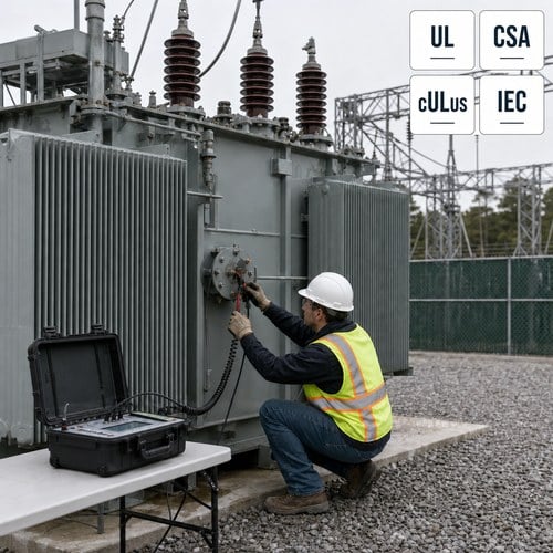
A transformer can pass a turns ratio test, pass an insulation resistance test, and still be mechanically damaged inside. The coils may have shifted a few millimetres during a fault, the oil may be perfectly dry, and every routine reading may look normal. The one test that answers the question “has anything moved inside the tank?” is frequency response analysis.
That question is more expensive to ignore than it used to be. Repair slots for large power transformers are booked far ahead, and re-energizing a unit with a displaced winding usually ends in a scrapped tank rather than a rewind. A defensible answer on winding condition is now a procurement decision, not a testing detail.
Why a Transformer Can Pass Every Routine Test and Still Be Damaged
When a close-in fault drives current through a winding, the electromagnetic forces between conductors scale with the square of that current. A 25 MVA unit carrying a 20 kA fault current develops radial and axial forces measured in tonnes. The insulation system is often not the weak point in that event. The mechanical structure of the winding is.
Here is the part most buyers miss. A turns ratio test measures the ratio of turns, not their position. A winding can be radially deformed into a hoop-buckled shape and still produce a ratio within half a percent of nameplate. Winding resistance may shift by a fraction of a percent — a signal, but rarely a convincing one on its own. Dissolved gas analysis needs heat and time before it produces gas to measure. All three can read clean on a unit that has already lost its mechanical margin.
Then the unit goes back into service. Load cycling works on the displaced conductor, paper insulation abrades against pressboard, and two years later a turn-to-turn fault appears. The failure gets recorded as insulation aging. The actual cause was a mechanical event nobody measured.
What an SFRA Test Actually Measures
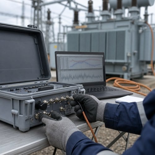
An SFRA test treats the transformer as an electrical network and measures how it responds over a very wide frequency range. A low-voltage swept sine signal is injected at one winding terminal and the response is measured at the other end. The sweep runs from 20 Hz to roughly 2 MHz, and the result is a transfer function plotted in decibels against a logarithmic frequency axis.
Nothing is energized at power frequency. The unit stays de-energized, grounded and connected only to the test set, which is why the test can be run on site without an outage window beyond the switching itself.
The measurement side is standardized. IEC 60076-18:2012 defines the measurement technique and the equipment for a frequency response measurement, on site or in the factory, on a new unit or one that has been in service for decades — the scope is set out on the IEC 60076-18 publication page (https://webstore.iec.ch/en/publication/597). Interpretation is handled separately by IEEE C57.149, revised as IEEE C57.149-2024 (https://standards.ieee.org/ieee/C57.149/7354/), which addresses oil-immersed transformers specifically.
One frequency response analysis result means very little on its own. The trace becomes useful only against a reference: the factory fingerprint taken before the unit shipped, the other two phases of the same transformer, or a sister unit built to the same drawing. That is why a baseline measured in the factory is worth more than any single field test, and why pasting a loose trace into a report achieves nothing.
Reading the Three Frequency Bands
Practitioners split the trace into three zones, because each zone is dominated by a different part of the transformer’s construction. Work through them in order and the picture usually becomes clear.
Below roughly 2 kHz the response is dominated by the magnetic circuit — the core and the magnetizing inductance. Deviations here point at core problems: core movement, shorted laminations, residual magnetism left by a DC test, or a winding-to-core short. A core that has shifted on its clamping structure produces a low-frequency shift that no other routine test catches.
Between about 2 kHz and 20 kHz the curve reflects winding geometry. This is the band where winding deformation shows up: radial deformation from hoop buckling, axial displacement of discs, variation in disc spacing, or a partially shorted winding section. A unit that took a heavy through-fault usually declares itself here first.
Above roughly 20 kHz the trace is driven by lead routing, bushing capacitance, tap changer position and the grounding of the test setup. It is also the band that generates most false alarms, because leads dressed differently from the baseline measurement move the trace while nothing is wrong inside the tank.
That last point is the practical trap. The most common cause of a reported winding deformation is a test run with the tap changer in a different position than the baseline. The second most common is a ground connection made at a different point on the tank. Both are setup errors, not equipment failures, and both disappear if the setup is documented alongside the trace.
How FRA Fits With Ratio, Resistance and DGA
An SFRA test does not replace the routine transformer diagnostics you already run. It fills the gap they leave. Used together, the set produces a condition assessment that holds up when a project manager or an insurer starts asking questions.
| Test | What it detects | What it cannot see |
| Turns ratio (TTR) | Shorted turns, wrong tap position, ratio errors | Radial or axial winding movement |
| Winding resistance | Open circuits, loose connections, tap changer contact wear, severe turn damage | Small geometric displacement |
| Insulation resistance / PI | Moisture, contamination, gross insulation degradation | Mechanical movement of the winding |
| Dissolved gas analysis (DGA) | Active thermal or electrical faults, once gas has formed | A winding that has moved but has not yet faulted |
| SFRA / FRA | Changes in winding and core geometry, lead routing, tap changer state | The exact location of damage without further investigation |
The working rule after a through-fault is to run ratio, winding resistance, DGA and FRA as one package and read them against each other. A clean ratio with a deviating FRA trace is the classic signature of winding deformation, and it is that combination which justifies opening a unit instead of returning it to service.
When to Run a Frequency Response Analysis
Five moments in a transformer’s life pay back the cost of the test, and every one of them belongs inside a condition-based transformer diagnostics program rather than in a reaction to something going wrong.
- After a through-fault, or any event where transformer protection operated. Set the trigger inside your maintenance standard before you need it — a common threshold is a fault current above the level the winding was designed to withstand.
- On receipt of a new unit at site. Compare the arrival trace against the factory fingerprint before you accept delivery. If the traces diverge, you hold a documented transport claim while the truck is still in the yard.
- After transport or extended storage, particularly for units that travelled overland for thousands of kilometres.
- Before and after any work that disturbs the active part: a rewind, a tank repair, a tap changer overhaul, a bushing replacement.
- On a repeating schedule for critical fleet units — the ones whose failure would take a data hall, a refinery process line or a hospital’s essential power system down.
Where Ryan Electric Fits: The Baseline Starts in the Factory
A baseline trace is only as good as the record behind it, and that record has to be created before the unit ships. In our test bay, every oil immersed transformer we build gets a frequency response measurement taken with the tap position, lead configuration and grounding points written into the test report. Without that record, a field crew five years later has nothing to compare against, and a genuine winding deformation looks exactly like a setup difference.
As an oil immersed transformer factory in China supplying North America, Southeast Asia, the Middle East and Africa, we build and test at a 120,000 m² plant with more than 180 sets of production and test equipment and 37 patents behind the design work. Units are type tested and routine tested against UL, CSA, IEEE, DEKRA and IEC requirements, and the test records travel with the shipment instead of staying in a filing cabinet at the works. Since 2023 we have also manufactured through a joint venture with Eaton, which puts a second set of eyes on the documentation before anything leaves the floor.
That matters most at the moment you need it: a unit coming back after a fault, a dispute over transport damage, or a decision on whether an aging asset can survive another five years of load growth.
What to Ask Before You Accept a Repair Quote
When a transformer returns from a fault and someone quotes a repair, the FRA data is what separates a diagnosis from a guess. Five questions are worth asking every time.
- Can I see the pre-fault baseline and the post-fault trace plotted on the same scale and the same axes?
- Was the tap changer position recorded, and was it identical in both measurements?
- Which frequency band shows the deviation, and what does that band correspond to physically?
- Did you run ratio, winding resistance and DGA at the same time, and do they agree with the FRA result?
- If the unit goes back into service without repair, what evidence supports that decision?
A supplier who cannot answer the first two questions is not doing condition assessment. They are guessing with test equipment.
The Cost of Skipping the Test
A frequency response analysis sweep takes minutes. Setup, lead dressing, documentation and comparison against the baseline usually take longer than the measurement itself — budget one to three hours per unit including preparation, depending on how accessible the bushings are. Against that cost, you are buying a decision: repair, re-energize, or replace.
With lead times where they are, that decision carries real money. Send us the rating, the voltage class and the fault history, and we will show you what our test records look like for a comparable oil immersed transformer and what the trace from your unit should look like in each frequency band. Start with the power transformer range at https://www.ryantransformers.com/power-transformer or email [email protected] and our engineering team will take it from there.
About the Author
This guide was prepared by the test and engineering team at Ryan Electric, based on factory acceptance testing and field commissioning support for oil-immersed and dry type transformers supplied to utility, data center, renewable and industrial projects. Questions about FRA baselines, test records or an active winding deformation case can be sent to [email protected].
Table of Contents
- Why a Transformer Can Pass Every Routine Test and Still Be Damaged
- What an SFRA Test Actually Measures
- Reading the Three Frequency Bands
- How FRA Fits With Ratio, Resistance and DGA
- When to Run a Frequency Response Analysis
- Where Ryan Electric Fits: The Baseline Starts in the Factory
- What to Ask Before You Accept a Repair Quote
- The Cost of Skipping the Test
- About the Author