
 EN
EN
The two transformers were identical on paper: 1,250 kVA each, 13.8 kV to 480Y/277 V, impedance within half a percentage point of each other. They still could not be operated in parallel. The reason was one line on the nameplate — the transformer vector group — where the installed unit reads Dyn11 and the spare we were asked to match reads Dyn1. In three-phase work that clock number decides whether two units are twins or strangers, and it is the line most often left blank on the enquiry.
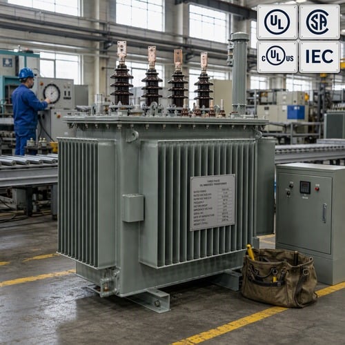
What a Transformer Vector Group Actually Tells You
The letters describe the winding connections and the number describes the phase displacement. Uppercase letters belong to the HV winding, lowercase to the LV winding: D and d mean delta, Y and y mean star, Z and z mean zigzag, and a small n means the neutral point is brought out and terminated. So a transformer vector group written as Dyn11 is a delta HV winding, a star LV winding with the neutral brought out, and a phase displacement of 11 × 30 = 330 degrees.
The clock convention is defined with the connection symbols in IEC 60076-1 (https://webstore.iec.ch/en/publication/588/). Picture the HV phasor pointing at twelve o’clock; the LV phasor sits at the hour given by the number. Eleven o’clock is 330 degrees, which is the same as saying the LV leads the HV by 30 degrees. One o’clock is 30 degrees the other way, so in a Dyn1 unit the LV lags the HV by 30 degrees. Both are legitimate and both are extremely common. They are also 60 degrees apart from each other, not 0 degrees, which is the detail that catches people out.
None of this is a setting you can change at commissioning. The group falls out of how the windings are physically connected inside the tank and how the leads are brought to the terminals, so it is fixed at the design stage, marked on the nameplate and confirmed by a factory test. On a mixed order you will also meet YNd11 (star HV with neutral, delta LV) on step-up duty, Yzn11 for zigzag secondaries, and Dd0 for delta-to-delta industrial units.
The Vector Groups You Will Meet on Real Projects
Six groups cover almost everything that crosses our test bay. The table below is the practical version we send to project engineers when they ask which group to write into a specification.
| Vector group | Phase displacement (LV relative to HV) | Where you see it | Why it is chosen |
| Yyn0 | 0 degrees, in phase | Small distribution units and LV networks that must stay in phase with the HV supply | Simple four-wire supply, but no delta winding to absorb triplen harmonics |
| Dyn1 | LV lags HV by 30 degrees | Three-phase distribution and pad-mounted units built to North American practice | The familiar ANSI and CSA distribution arrangement; the delta traps triplen harmonics |
| Dyn11 | LV leads HV by 30 degrees | European and IEC-practice distribution networks, and most export projects | The default IEC distribution group, with the same harmonic benefit as Dyn1 |
| YNd11 | LV leads HV by 30 degrees | Generator step-up and transmission transformers, HV star with grounded neutral | Gives a grounded HV neutral for the system, with a delta LV winding |
| Yzn11 / Dz0 | LV leads by 30 degrees / in phase | Units feeding heavily unbalanced four-wire LV load | Zigzag secondary carries zero-sequence current without overheating |
| Dd0 + Dy11 | 30 degrees between the two secondaries | Rectifier and twelve-pulse drive transformers | The 30 degrees between secondaries cancels the fifth and seventh harmonics |
The pattern that causes the most trouble is regional. North American distribution practice settles on Dyn1, where the LV lags the HV by 30 degrees; IEC and European practice settles on Dyn11, where it leads. Both are correct, and a single-line diagram often carries only the winding letters without the clock number. If a specification says “delta-wye” and nothing else, the supplier will build to the local convention, and a spare ordered from a different country can arrive 60 degrees away from the unit it is meant to back up.
So write the full symbol. Dyn11, not “delta-wye”. Add the neutral requirement, because Dd or Dy without an n means no neutral terminal at all, which changes how the LV system is earthed and what the protection sees. The extra six characters on the drawing cost nothing at quotation stage and cannot be fixed afterwards without a factory reconnection and a fresh test.
Why the Clock Number Decides Whether Two Units Can Run in Parallel
Four conditions have to hold before two transformers can share a bus. They must have the same phase displacement, the same voltage ratio, closely matched impedance, and identical tap positions. Only the first is absolute. The parallel-operation guidance in IEC 60076-8 (https://webstore.iec.ch/en/publication/606/) treats the question in exactly this order: the connection group has to agree, the ratio has to agree within a fraction of a percent, and the impedances have to be close enough that neither unit is pushed past its rating.
Here is what a mismatch actually does. Take two 1,000 kVA units with a rated secondary of 480 V and 5.5% impedance. If their groups differ by 30 degrees, the two secondary voltages sit at different phase angles, and the voltage between the corresponding phases of the two machines is 2 × 480 × sin 15 degrees, or about 52% of rated voltage. Divide that by the sum of the two impedances and the circulating current is roughly 4.7 times rated current — before any load is connected. If the two clock numbers are 60 degrees apart — a Dyn1 unit next to a Dyn11 transformer — the two voltages are a full rated voltage apart and the circulating current approaches nine times rated current. Closing the paralleling device in that state is not a commissioning nuisance; it is a short circuit with a switch on it.
Ratio and impedance mismatches are quieter but expensive. A ratio difference of 1% between two otherwise identical units drives a circulating current of roughly 9% of rated current at 5.5% impedance, which shows up as extra no-load loss and a warm transformer that has no load on it. An impedance mismatch does not stop the units running together at all, it just decides who works harder: with equal ratios, load shares in inverse proportion to impedance, so the lower-impedance unit reaches full load while its partner is still carrying less. That is how a transformer gets overloaded on a site where every nameplate looks correct.
Harmonics, Earthing and Unbalanced Load: The Second Reason the Group Matters
The winding arrangement does more than rotate a phasor. In a Dyn unit the delta-connected HV winding gives third-harmonic and zero-sequence currents a closed path inside the transformer, so the secondary voltage stays close to sinusoidal even when the core is driven hard. In a Yyn unit with no delta winding and no tertiary, those same currents have nowhere to circulate in the windings and instead push the neutral point around, which is why Yyn designs are normally kept to smaller distribution ratings and are a poor match for a plant full of variable frequency drives.
The delta also carries the zero-sequence path that makes earth-fault protection work. On a Dyn transformer, a downstream LV earth fault produces a current that the HV-side protection can see and quantify, because the delta provides the return path. Choose a group without that path and the fault current has to find its way through the earthing arrangement instead, which usually means a slower or less sensitive protection setting. Whether the neutral is brought out at all — the n in Dyn11 — decides if you have a four-wire LV system, a neutral terminal for a grounding resistor, or a three-wire load that must be earthed elsewhere.
Two more cases come up often enough to plan for. Facilities with heavy single-phase LV load, such as a commercial building with a large lighting and socket demand on one phase, are better served by zigzag groups like Yzn11, which are built to carry zero-sequence current continuously. And a twelve-pulse rectifier or large DC drive is normally fed from a three-winding transformer whose two secondaries are 30 degrees apart, because that displacement is what cancels the fifth and seventh harmonics before they reach the supply. Both choices are settled at specification stage; neither is a retrofit.
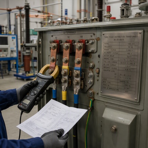
What to Put in the Specification, and How to Verify It
Five lines in the enquiry remove almost all of the risk. First, the full connection symbol with the clock number, for example Dyn11, plus the neutral requirement. Second, the tap range and whether the unit must run on the same tap as an existing transformer — a spare that matches in every respect except tap position is still not a parallelable spare. Third, the required impedance with a stated tolerance, because a band of 5.5% to 6% is a different product from “about 6%”. Fourth, the fault level the LV winding must withstand, since the group interacts with the earthing and protection scheme. Fifth, the phase sequence and terminal marking convention you want, because North American and IEC terminal designations are not the same thing.
Verification is straightforward, and it is a routine test rather than a special one. IEC 60076-1 includes the measurement of voltage ratio and the check of phase displacement, and IEEE C57.12.90 lists ratio tests and polarity and phase-relation tests among the measurements made on liquid-immersed units. Ask for the test record that shows the phase displacement the unit was actually measured at, not only the ratio figures. A test sheet that reports three ratios and no connection check tells you nothing about whether the group matches the drawing.
Then read the nameplate against the test sheet before the unit leaves the factory. The connection symbol, the ratio, the impedance, the tap table and the vector group should all trace back to the same test record, and the plate should carry the certification mark the project requires — a cULus or CSA mark for a Canadian or US installation, with CSA C227.4 setting out the requirements for three-phase pad-mounted distribution units. You can run that check yourself in the UL Solutions certification search at https://www.ul.com/, and it is worth doing before you accept a nameplate photograph as proof. This is also the moment to photograph the plate and file it, because the photograph becomes the reference for the next spare you order.
How We Build and Test Custom Three-Phase Units
Ryan Electric has been building transformers since 2007 in a 120,000 m² facility with more than 180 sets of production and test equipment and 37 patents, working to UL, CSA, IEEE, DEKRA, CNAS and CE requirements. As a UL listed transformer supplier, we ship cULus-marked and CSA-compliant units into North American projects, and the transformer vector group on every unit is proved in the bay before the tank is painted. Ratio and phase-relation testing runs on each three-phase unit, the measured displacement is recorded on the routine test sheet, and the nameplate is checked against that sheet rather than against the drawing, which is where mismatches hide.
Most of the custom work we do is not exotic. It is a project that needs a Dyn11 transformer to match a European-designed switchboard, or a Dyn1 unit to sit beside a North American pad-mounted transformer on the same bus, or a spare built to match an installed unit whose nameplate is the only surviving record of how it was connected. Since 2023 we have also operated as an official joint-venture partner of Eaton, which matters mainly for one reason: the documentation and test records a joint venture partner is expected to keep are the same records a project engineer needs when a paralleling question arrives three years after commissioning.
The Next Step
Send us two things and the answer usually takes a day. The nameplate photograph of the transformer you already have — including the connection symbol and the tap table — and the single-line diagram for the bus the new unit will connect to. With those, our engineers will confirm the group you need, tell you whether an off-the-shelf Dyn11 transformer or a Dyn1 build is the right match, and put the ratio, impedance tolerance and tap range that make parallel operation possible into writing.
If you are specifying from scratch and have not settled the connection symbol, that is the right time to raise it. The transformer vector group is decided by the drawing and confirmed by a test, so it is free to get right at quotation stage. Ask for a marked-up specification review, or send the ratings you are working with and we will come back with the group, the impedance band and the test plan for your project.
About the Author
This guide was prepared by the application engineering team at Ryan Electric, a UL listed transformer supplier working with utility, industrial, data centre and renewable projects across North America, the Middle East, Southeast Asia and Africa. Our engineers have supervised factory acceptance testing for oil-immersed and dry-type units from 500 kVA to 200 MVA, including ratio and phase-relation verification on three-phase builds. Send the drawings, the motor schedule and an existing nameplate photograph to our engineering desk for a review before you issue the purchase order.
Table of Contents
- What a Transformer Vector Group Actually Tells You
- The Vector Groups You Will Meet on Real Projects
- Why the Clock Number Decides Whether Two Units Can Run in Parallel
- Harmonics, Earthing and Unbalanced Load: The Second Reason the Group Matters
- What to Put in the Specification, and How to Verify It
- How We Build and Test Custom Three-Phase Units
- The Next Step