
 EN
EN
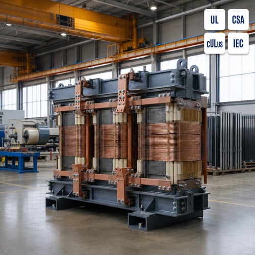
Almost every rail project reaches the same fork. A traction transformer is specified for a substation, and then one sentence arrives that rewrites the whole layout: the unit rides on the vehicle. That line moves the machine from a concrete pad behind a mesh fence to a steel frame bolted under a car body, and it changes the thermal, mechanical, and certification logic you started with.
On-Board and Trackside Are Two Different Engineering Problems
These machines split into two families that share a name and almost nothing else. On-board units travel with the train and are fed from an overhead catenary or a third rail. Trackside units sit in a traction substation and feed the catenary itself. When a buyer asks one supplier to quote both without separating the duty, the result is usually two incompatible designs lined up in the same comparison table.
Voltages tell the story. European mainline networks run 15 kV at 16.7 Hz, while most other electrified systems run 25 kV at 50 Hz. On board, that catenary voltage steps down to roughly 1.5 kV for the traction converter, with separate secondary windings at around 400 V feeding HVAC, lighting, and compressors. DC railways at 750 V, 1.5 kV, and 3 kV convert power trackside instead, so the on-board transformer's main job there is auxiliary supply rather than traction.
The design drivers point in opposite directions. A trackside unit is sized by short-circuit withstand and thermal margin, and there is usually room on the plinth to make it larger. An on-board unit is sized by mass and volume, because every kilogram of core and winding is mass the bogie carries and energy the train spends accelerating it.
What IEC 60310:2026 Changed — and Why Your Traction Transformer Spec Needs a Second Look
On-board traction transformer design is governed by IEC 60310. The fifth edition was published on 13 April 2026 and cancels the 2016 fourth edition. This is a technical revision rather than an editorial refresh, and the published scope is set out on the IEC 60310:2026 webstore page.
Six changes matter to anyone writing or reviewing a technical specification. Typical circuits for transformers and inductors have been added, which gives designers a shared reference for the common winding arrangements. Letter symbols for cooling methods are now defined. The dielectric test table has been modified. The test subclauses have been restructured. Temperature testing for dry-type transformers and dry-type inductors has been split into two separate subclauses. Shock and vibration requirements have been updated against IEC 61373.
That last item is the one that catches projects out. If your factory acceptance test plan was written against the 2016 edition and treated dry-type temperature testing as a single clause, the plan no longer matches the standard your customer is citing. The scope line is worth reading too: IEC 60310 does not apply to instrument transformers, to transformers rated below 1 kVA single-phase or 5 kVA polyphase, or to small inductors.
Liquid-Immersed or Dry Type: Make the Cooling Decision First
On-board units are usually liquid-immersed, in mineral oil or an ester fluid, because liquid circulation carries heat away from the winding far more effectively than air and produces the highest power per kilogram. On a vehicle, that efficiency is worth the complexity of a sealed tank and the maintenance it implies.
There is a firm place for the dry type transformer in rail work, though, and it is not a fallback. Tunnels, underground stations, and any location where a fluid spill or a large fire load is unacceptable push the specification toward VPI or cast resin construction. The same logic applies to auxiliary and station transformers mounted inside a public building.
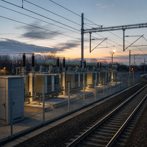
Trackside, the oil immersed transformer still dominates mainline substations at 25 kV and rectifier duty on DC networks, because the unit sits inside a fenced compound where thermal margin matters far more than mass. For those applications, cooling class selection — ONAN alone, or ONAN with forced-air stages — is what sets the continuous rating.
In our own design reviews, the cooling decision is often the last item locked and the first item that should have been. Settle it before the winding layout: whether the answer is a liquid-immersed tank or a dry type transformer in an IP-rated enclosure, the cooling choice fixes the insulation system, the geometry, and the clearances that everything else has to fit around.
The Spec Sheet Items That Decide Whether the Unit Fits
Two units can carry the same kVA rating and still be wrong for each other's duty. The table below is the short version of what changes when a traction transformer moves from a substation plinth to a vehicle.
| Specification item | On-board unit | Trackside unit |
|---|---|---|
| Input | 25 kV 50 Hz, or 15 kV 16.7 Hz catenary | 25 kV, 15 kV, 33 kV, or 11 kV |
| Typical secondary | About 1.5 kV for the traction converter; about 400 V auxiliary | 1.5 kV DC or 750 V DC rectifier feed; 11 kV distribution |
| Dominant design driver | Mass and volume | Short-circuit withstand and thermal margin |
| Cooling | Liquid-immersed, or VPI / cast resin dry type | Oil-immersed ONAN or ONAF; dry type indoors |
| Governing standard | IEC 60310:2026 | EN 50329 with IEC 60076 |
| Mechanical qualification | IEC 61373 shock and vibration | Seismic qualification where the site demands it |
| Insulation coordination | Tight clearances, high dv/dt from the converter | BIL-driven clearances |
| Fire and spill constraint | Tunnel and passenger-area rules | Substation separation rules |
Percent impedance decides more arguments than any other line on the data sheet. On board, a higher impedance limits fault current and protects the converter, but it also increases regulation and load loss. Trackside, impedance has to be matched to the protection settings and to any parallel unit, because mismatch shows up as unequal load sharing the first time both transformers are energised together — and the weaker unit runs hot from day one.
Write the impedance tolerance into the purchase order, not only the nominal value, and state the tap range explicitly. A transformer built around one supply voltage rarely performs well when the network is later re-fed from a different feeder.
Certification and Factory Testing for Rail Projects
North American transit and industrial projects layer their own approvals on top of the IEC framework. ANSI/UL 1561 covers dry-type general purpose and power transformers, and its published scope stops at a nominal primary or secondary rating of 600 V, so anything above that level follows a different certification path. Edition 4 is current, last revised on 31 August 2023, and the scope text is published on the UL 1561 standard page.
Beyond the listing itself, what separates a smooth project from a painful one is the test package. For a dry type transformer we would expect ratio and polarity, winding resistance on every winding, insulation resistance, separate-source AC withstand, induced overvoltage, partial discharge measurement with the pC limit named in the purchase order, and a temperature-rise test. An oil immersed transformer adds oil testing and a pressure or leak test on the tank. Type tests such as lightning impulse and short-circuit withstand should be evidenced by a report from a recognised laboratory rather than promised in a quotation.
The sequence matters as much as the list. Buyers who leave it unspecified sometimes receive a partial discharge figure measured on a cold unit when what they wanted was the post-temperature-rise value, and the two numbers are not interchangeable in a design review.
Why These Units Are Built to Order
Catalogue designs rarely fit rail work. Gauge constraints, multiple secondary windings, a specific impedance window, auxiliary windings at an unusual voltage, and a mounting arrangement dictated by the car builder all push a project toward a custom three phase transformer built to project drawings instead of selected from a data sheet.
Ryan Electric has manufactured transformers since 2007 and has operated as an official joint-venture partner of Eaton since 2023, an arrangement that places an established North American engineering and quality framework behind the same production lines. The manufacturing base covers 120,000 m² with more than 180 sets of production and test equipment, and the company holds UL, CSA, IEEE, DEKRA, CNAS, and CE certification.
For rail enquiries we build the design review around three questions before anything else: what mass the mounting point can carry, what fault current the windings must survive, and what ambient and ventilation conditions the installation actually provides. Getting those three answers first removes most of the redesign work later.
Procurement Timing for Rail Transformer Orders
Rail programmes run on fixed approval gates, and the traction transformer is rarely on the critical path until the moment it suddenly is. The car builder freezes the underframe layout, the substation design freezes the plinth and cable routes, and both dates typically land well after the commercial contract is signed. Ordering at that point compresses manufacturing into whatever window is left.
The buyers who avoid that problem place the order at design freeze rather than at construction release, and they accept that a small part of the design may still move. They also pull the long-lead item out of the main package, so a late change to the signalling or civil scope cannot delay the transformer.
If you are preparing a rail or transit enquiry, send us the duty, the mounting or plinth constraints, the fault level, and the ambient conditions. We will come back with a custom three phase transformer proposal that fits the first time — you can reach our engineering team through the contact form on our homepage.
About the Author
This article was prepared by the engineering content team at Ryan Electric, a transformer manufacturer established in 2007 and an official joint-venture partner of Eaton since 2023. The team supports utilities, EPC contractors, and transit projects across North America, the Middle East, Southeast Asia, and Africa with custom dry-type and oil-immersed transformer designs. For technical enquiries, contact the engineering team through the Ryan Electric website.
Table of Contents
- On-Board and Trackside Are Two Different Engineering Problems
- What IEC 60310:2026 Changed — and Why Your Traction Transformer Spec Needs a Second Look
- Liquid-Immersed or Dry Type: Make the Cooling Decision First
- The Spec Sheet Items That Decide Whether the Unit Fits
- Certification and Factory Testing for Rail Projects
- Why These Units Are Built to Order
- Procurement Timing for Rail Transformer Orders
- About the Author