
 EN
EN
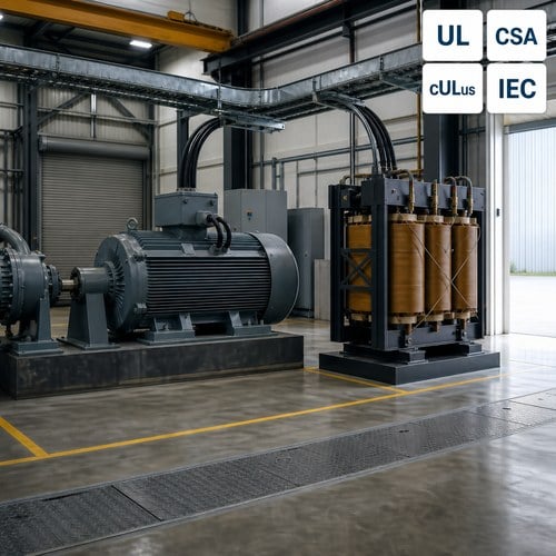
Transformer Sizing for Motor Starting: Voltage Dip, Locked Rotor Current, and Impedance Explained
A food processing plant in the Gulf sent us a one-line diagram last quarter with three 200 hp motors on a single 1,000 kVA transformer, all started direct-on-line. The transformer matched the running load with room to spare. The failure appeared on the first start of the day: the 480 V bus sagged far enough that the line contactors opened, the motor never reached full speed, and the plant sat waiting for an electrician. Nothing was broken. The transformer sizing for motor starting had simply never been calculated.
That gap is normal, and it is expensive. A motor nameplate tells you the horsepower and the full-load amps. It does not tell you the kVA the transformer has to deliver during the seconds that the rotor is accelerating — and that number, not the running load, is usually what decides whether the bus holds.
Why Motor Starting Is a Transformer Problem
A running motor and a starting motor are two different loads wearing the same nameplate. At speed, an induction motor draws close to full-load current at a power factor near 0.85 to 0.9, and the load is mostly real power. At standstill, rotor impedance collapses, current jumps to roughly six times full-load current for a NEMA Design B motor, and the power factor falls to somewhere between 0.15 and 0.3.
A starting motor draws almost pure reactive current. To the transformer and the bus it looks like a large inductance switched on in one step, and reactive current is exactly what produces voltage drop across transformer impedance.
Here is the part most buyers miss: this is not a motor defect and it is not something the motor supplier can fix with a better insulation class. The dip is a system property. It depends on the ratio between the motor's starting kVA and the transformer's short-circuit capacity, which makes transformer sizing for motor starting a specification decision made on the transformer side of the drawing.
The same physical event shapes the standard both parties work from. NEMA MG 1 assigns every motor a locked-rotor kVA code letter and defines the starting performance users can rely on — a useful reference when a supplier question turns into a contract question. The NEMA Motor & Generator standards program publishes the document.
Reading the Starting Load Off the Motor Nameplate
The code letter is the fastest way to get locked-rotor kVA without a motor data sheet.
It converts horsepower straight into locked-rotor kVA, and it appears on the nameplate of every NEMA motor.
| Code letter | Locked-rotor kVA per hp |
| E | 4.5 – 4.99 |
| F | 5.0 – 5.59 |
| G | 5.6 – 6.29 |
| H | 6.3 – 7.09 |
| J | 7.1 – 7.99 |
| K | 8.0 – 8.99 |
The scale runs from A to V and climbs with each letter, so a code K motor asks about 60% more from the transformer than a code F motor of the same rating. A 200 hp unit with code F sits at 1,000 to 1,118 kVA of starting demand; the same 200 hp with code K reaches 1,600 to 1,798 kVA. Read the letter off the actual nameplate rather than from a catalogue, because it is the one number that moves the sizing conclusion on its own.
Three more details belong next to it:
- Starts per hour. Each start is a thermal event in both the motor and the transformer winding. Motor manufacturers publish a permitted starts-per-hour curve, and the transformer has to survive the same duty.
- Load torque characteristic. A centrifugal pump starts almost unloaded; a loaded conveyor, a positive-displacement compressor or a high-inertia fan can sit in the accelerating band long enough to matter.
- Starting method. Direct-on-line, autotransformer, wye-delta, soft starter and variable frequency drive each put a different current profile on the transformer.
Transformer Sizing for Motor Starting: The Calculation Every RFQ Should Carry
The screening calculation is short enough to do by hand. Transformer short-circuit capacity is its kVA divided by per-unit impedance; starting kVA divided by that capacity, expressed as a percentage, gives the approximate voltage dip:
%Voltage dip ≈ (Motor starting kVA × Transformer %Z) ÷ Transformer kVA
Worked through the pumping station case at 5.75% impedance, with one 200 hp code F motor starting while the other two run:
| Transformer | Short-circuit capacity | Starting kVA | Calculated dip |
| 500 kVA | 8,696 kVA | 1,060 kVA | 12.2% |
| 750 kVA | 13,043 kVA | 1,060 kVA | 8.1% |
| 1,000 kVA | 17,391 kVA | 1,060 kVA | 6.1% |
Three points stand out. First, dip moves almost linearly with transformer kVA, so the sizing decision is the dip decision. Second, impedance is a lever of its own: at 500 kVA, dropping impedance from 5.75% to 4.0% pulls the dip back to about 8.5% without buying a larger unit. Third, this is a screening check, not a substitute for a study. It ignores the utility source impedance and the running motors already on the bus, and both of those add to the real dip — so keep margin on the result instead of treating it as the final number.
Run the same arithmetic for every motor that can start while the plant is at full load, then again for the worst credible combination. Utilities and consultants will run the full study; a transformer supplier that cannot reproduce this check is quoting a kVA, not a system.
How Much Dip Is Acceptable, and What Actually Trips
The screening target most industrial projects use is a voltage dip of 10% or less at the motor terminals during starting. On a dedicated feeder where nothing sensitive shares the bus, 15% is sometimes accepted, but that is a decision the plant's electrical engineer should make in writing rather than discover during commissioning.
The reason the limit is tighter than the motor needs is that the motor is rarely the first thing to complain:
- Contactors are typically rated to hold in down to about 85% of coil voltage, so a 15% dip can open a starter that the motor itself would have survived.
- Variable frequency drives and power supplies ride through a dip only for the hold-up time of their DC bus.
- Undervoltage relays protecting other equipment are often set to trip above 20% dip, which turns a start into a plant-wide trip.
- Utility flicker limits can constrain repeated starts at a shared service, even when every load on site tolerates the dip.
Motor protection during the start is its own subject, and the industry reference is IEEE 3004.8, the Recommended Practice for Motor Protection in Industrial and Commercial Power Systems, which covers starting, bus transfer and undervoltage protection for both contactor-controlled and breaker-controlled starters.
Spec Decisions That Actually Fix the Dip
Once the numbers are on the table, the options sort themselves by cost and side effects.
- Buy more kVA. Directly proportional, simple, and it also raises the available fault current, which may force a review of downstream equipment ratings.
- Specify lower impedance. Effective, but lower %Z means higher fault current and higher mechanical forces on the windings during a short circuit. Specify it as a target with a tolerance, not as a wish.
- Give the large motor its own transformer. Isolation is often cheaper than oversizing a shared unit, and it keeps a pump start from disturbing a process line.
- Choose the starting method deliberately. An autotransformer starter on the 65% tap cuts the line current to roughly 42% of direct-on-line, because torque and line current both scale with the square of applied voltage. Wye-delta delivers about a third of direct-on-line current. A soft starter or a drive gives the smoothest profile but adds its own harmonic and protection considerations on the transformer.
- Check the thermal duty, not just the dip. Repeated starts heat the winding. A transformer that passes a single-start calculation can still fail a specification that calls for six starts per hour at full ambient.
- Do not expect motor efficiency to help. A NEMA Premium motor cuts running losses — the reason the U.S. Department of Energy maintains its Motor Systems resource program — but it does not reduce locked-rotor kVA. Starting performance and running efficiency are separate nameplate specifications.
Note the difference from energization inrush. The reactor-thrashing current that trips a breaker when an unloaded transformer is switched on is a separate phenomenon with its own spec implications, covered in our guide to transformer inrush current. Both show up on the same project; neither is solved by the other.
How Ryan Electric Approaches Motor Load Projects
Ryan Electric (Jiangsu Ryan Electric Co., Ltd.) has built transformers since 2007 and has worked as an official joint-venture partner of Eaton since 2023. Motor-heavy industrial projects usually arrive as a power transformer or distribution transformer requirement with an impedance target and a starting duty attached, and that is the part of the quotation our engineers spend their time on.
Most of the work is in the front end. We ask for the motor schedule — horsepower, code letter, voltage and starting method — before we quote a kVA, because impedance selection and winding design follow from the transformer sizing for motor starting calculation, not from a catalogue page. Where a project needs a specific impedance band, an unusual tap range or a dual-voltage secondary, that design runs through the same custom engineering process we use for rectifier and furnace duty. Certification coverage includes UL, CSA, IEEE, DEKRA, CNAS and CE, and every unit ships with routine test data — ratio, winding resistance, impedance, no-load loss, load loss and dielectric tests — so the commissioning team can verify the delivered impedance against the number the study was based on.
What to Put in the RFQ
Five items turn a vague enquiry into a quotable transformer specification:
- Motor schedule with horsepower, NEMA code letter, voltage, and Design letter or IEC starting class.
- Starting method and the resulting line current profile.
- Required starts per hour and the ambient design temperature.
- The acceptable voltage dip, and whether a motor starting study already exists.
- Available fault current at the primary, so that impedance and interrupting ratings can be coordinated together.
Send those five and the transformer quotation stops being a price comparison between assumptions. If you have a motor schedule and a one-line diagram, send them to us through our contact page and our engineering team will return a kVA and impedance recommendation with the dip calculation shown.
About the Author — This guide was prepared by the medium-voltage transformer engineering team at Jiangsu Ryan Electric Co., Ltd., a Nantong-based manufacturer of dry-type, oil-immersed, pad-mounted and compact substation products, and an official joint-venture partner of Eaton since 2023. The team supports industrial, utility and infrastructure projects from specification review through factory acceptance testing, and works on transformer designs from 10 kV to 110 kV class.
Table of Contents
- Transformer Sizing for Motor Starting: Voltage Dip, Locked Rotor Current, and Impedance Explained
- Why Motor Starting Is a Transformer Problem
- Reading the Starting Load Off the Motor Nameplate
- Transformer Sizing for Motor Starting: The Calculation Every RFQ Should Carry
- How Much Dip Is Acceptable, and What Actually Trips
- Spec Decisions That Actually Fix the Dip
- How Ryan Electric Approaches Motor Load Projects
- What to Put in the RFQ