
 EN
EN
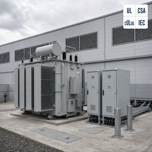
Battery plants are designed around chemistry and built around electricity, and the two do not forgive the same mistakes. The IEA put global nameplate lithium-ion manufacturing capacity above 4 TWh at the end of 2025, roughly 30% higher than the year before, and every TWh of that capacity is a factory that needs a firm, clean medium-voltage supply before a single cell is formed. The transformer for battery manufacturing decides how stable that supply is — not the switchgear, not the inverters. It sets the voltage the process actually sees.
Why a Gigafactory Is a Transformer Project First
Cell plants are usually built in phases, and the electrical design is the part that cannot be phased comfortably. A site that starts with two production lines is laid out for six, so the incoming gigafactory power distribution scheme has to carry a load that roughly doubles before the building is finished. Retrofitting medium-voltage capacity into a live plant costs far more than building it in from the start, which is why the transformer schedule is normally frozen before the process layout is final.
The load mix explains the rest. Dry rooms run dehumidification continuously, coating and drying ovens hold temperature profiles within tight bands, formation and aging areas convert AC to DC and back, and HVAC carries a large share of the connected load. Diversity across that mix is low compared with a general manufacturing plant, so the transformers sit at a high load factor for years. At that duty level, both no-load loss and load loss become commercial parameters rather than technical footnotes.
Inside the Load Profile: Formation, Dry Rooms and Regenerative Charging
Formation and aging drive the electrical character of a cell plant. Racks of chargers cycle thousands of cells at low voltage and high current, and modern lines discharge cells regeneratively, which means power flows back through the transformer instead of only outward. The rectifier front ends behind those chargers are non-linear loads: a classic six-pulse bridge injects characteristic fifth and seventh harmonic currents, and its displacement power factor falls away at part load. Multiply that by a few thousand channels and the harmonic environment becomes the dominant design condition for the area.
Dry rooms and ovens pull the opposite way. They are continuous, non-cyclic and intolerant of variation — a dehumidifier that loses control does not just waste energy, it puts the yield of everything inside the room at risk. That combination, a heavy non-linear block on one side and a stability-sensitive block on the other, is why battery plants are usually served by more transformers than a plant of similar total demand. Electrical segregation protects the process.
Here is the part most first-pass specifications miss. When a battery plant enquiry reaches our engineering desk, the first document we ask for is not the transformer schedule. It is the single-line diagram of the formation and aging area, plus the number of simultaneously charging racks. Sizing from the site’s total connected load gives a number that is technically correct and commercially useless, because the transformer that matters is the one feeding the rectifier banks.
Voltage Sag and Harmonics: The Two Specifications That Decide Yield
A voltage sag of a few cycles is enough to reset a programmable controller or abort a formation cycle, and the cost of that event is measured in scrapped cells and lost line time. Transformer selection cannot eliminate sags, but it decides how deep they arrive. Running a dedicated unit at a lower loading level reduces voltage drop through the transformer itself, separating the rectifier area from motor-heavy loads such as compressors limits how far a motor start propagates, and keeping the source impedance realistic avoids amplifying the event at the process bus. What a transformer spec should state is the maximum acceptable voltage variation at the formation bus, not simply the kVA.
Harmonics work on a slower timescale and cause more damage. IEEE 519 sets the voltage distortion limit at the point of common coupling, and pushing a rectifier-heavy plant inside that limit usually means choosing between three routes: twelve-pulse or active front-end rectifiers, a dedicated transformer for converter duty, or a K-factor / thermally uprated transformer that carries the additional harmonic losses without exceeding its winding temperature limit. The three are not interchangeable on price, and only the first changes what the load injects.
Monitoring is the last piece of the specification and the cheapest one to get wrong. Winding and oil temperature devices, plus a protection relay that records the event that tripped the line, turn a two-week fault investigation into a two-hour one. The same protection scope questions come up on industrial plants of every kind, and the answers are worth settling at specification stage rather than after the marshalling box is built — our oil-immersed protection guide covers the device list in detail.
Dry Type or Liquid Filled: Choosing Per Area, Not Per Plant
Battery plants rarely use one transformer type throughout. The cleanroom and dry-room side of a plant favours cast resin dry-type units built to IEC 60076-11, because there is no liquid to contain, the fire load inside the building stays low, and maintenance can be handled by plant electrical staff rather than an oil-handling contractor. What matters in that environment is the enclosure and the air path: resin windings tolerate humidity and dust far better than the room they sit in.
The outdoor substation side usually goes the other way. Above a few MVA, oil-immersed units with ONAN or ONAF cooling deliver a lower cost per MVA and documented overload headroom that dry-type units cannot match in the same footprint. For sites in humid or coastal locations, the oil preservation system deserves the same attention as the rating, and the trade-off between a sealed tank and a conservator system is a climate decision rather than a price decision.
| Plant area | Typical transformer choice | Primary reason |
|---|---|---|
| Dry room and indoor electrical rooms | Cast resin dry type, IP-rated enclosure | No liquid containment, low fire load inside the building |
| Formation and aging area | Converter-duty unit, K-factor or thermally uprated | Non-linear rectifier load and regenerative power flow |
| Outdoor main substation | Oil immersed, ONAN / ONAF, dual temperature rise | Cost per MVA and overload capability at higher ratings |
| Utility interface substation | Power transformer with on-load tap changer | Voltage regulation against a varying site load |
Standards and Documentation Battery Customers Actually Ask For
The technical baseline is familiar: the IEC 60076 series for the transformer, IEEE C57.12.00 and C57.12.90 for North American projects, and NFPA 70 for installation. Certification follows the destination market — a UL listing or cULus mark for United States and Canadian plants, CSA where Canada is the inspection authority. What is less familiar to suppliers outside the battery industry is the documentation discipline. Cell manufacturers apply automotive-grade expectations to their equipment vendors, so test records, material traceability and a signed routine test report are treated as part of the deliverable rather than as an afterthought.
Our position on this is simple: if a buyer has to ask twice for a nameplate-level test record, the supplier is not set up for battery projects. The values that get checked on arrival — impedance, temperature rise class, tap range and the exact loss figures — are the same ones that decide whether the plant’s energy model holds up, which is why they are worth reading before the unit ships rather than after. Our transformer nameplate guide walks through the fourteen ratings that matter.
How Ryan Electric Supports Battery Plant Projects
Jiangsu Ryan Electric has manufactured transformers since 2007 from a 120,000 m² plant with more than 180 sets of production and test equipment and 37 patents, and has been an official joint-venture partner of Eaton since 2023. Our customer base includes global technology and battery manufacturers such as CATL, which is one reason our engineers are comfortable working to an end customer’s own specification book rather than to a catalogue.
Battery plant work is custom work: cast resin dry-type units for indoor areas, oil-immersed ONAN / ONAF units for substations, converter-duty designs for rectifier-fed formation areas, 50 Hz and 60 Hz builds, dual temperature rise ratings, IP-rated enclosures, and UL- or CSA-listed construction for North American sites. Where a plant runs regenerative formation lines, we model the harmonic spectrum the rectifiers produce and document the additional winding loss instead of filing it under battery losses.
Every unit is routine tested to IEC 60076-1 or IEEE C57.12.90 — turns ratio, winding resistance, insulation resistance and polarisation index, applied and induced voltage withstand, and partial discharge measurement on dry-type designs — with temperature rise demonstrated on the design unit and impedance verified rather than assumed. Ryan Electric holds UL, CSA, IEEE, DEKRA, CNAS and CE credentials, and testing for North American projects is witnessed through the listing agency rather than signed off internally.
What to Put in a Transformer RFQ for a Battery Plant
Put these items in the enquiry and the technical comparison becomes a fair fight:
- Area-by-area load list: formation and aging, dry rooms, ovens, HVAC, compressed air
- Rectifier channel count and whether regenerative discharge is in scope
- Maximum acceptable voltage variation at the formation bus
- Harmonic spectrum expected at the point of common coupling, or the rectifier pulse number
- Ambient temperature and ventilation available in each room
- Redundancy philosophy: N, N+1 or 2N, and whether transformers are paralleled
- Certification market: UL, cULus, CSA, or IEC type test records only
- Documentation level expected by the end customer, including material traceability
Send those items with the formation area single-line diagram and the room layouts, and the technical clarification usually collapses to one or two questions. Our engineering desk answers enquiries within one working day, and the earlier the connection profile is frozen, the more of it can be absorbed into a normal production slot rather than an expedited one — the same reason 2026 lead times reward buyers who specify early.
About the Author: This article was prepared by the application engineering team at Ryan Electric (Jiangsu Ryan Electric Co., Ltd.), a transformer manufacturer founded in 2007 and an Eaton joint-venture partner since 2023. The team supports UL-, CSA- and IEEE-compliant projects across North America, Southeast Asia, the Middle East and Africa, with in-house routine and type testing under CNAS accreditation. For battery plant transformer sizing, a converter-duty review or a quotation, contact our engineering desk.
Table of Contents
- Why a Gigafactory Is a Transformer Project First
- Inside the Load Profile: Formation, Dry Rooms and Regenerative Charging
- Voltage Sag and Harmonics: The Two Specifications That Decide Yield
- Dry Type or Liquid Filled: Choosing Per Area, Not Per Plant
- Standards and Documentation Battery Customers Actually Ask For
- How Ryan Electric Supports Battery Plant Projects
- What to Put in a Transformer RFQ for a Battery Plant