
 EN
EN
A grinding station in West Africa asked us to re-quote an 8 MVA unit last quarter. The original cement plant transformer had been ordered off the mill’s running load, and for eleven months it had been dropping the bus voltage far enough on every raw mill start that the mill starter refused to hold in. Nobody had measured the starting kVA. Everybody had assumed the transformer was the problem — or worse, assumed it was not.
Cement is one of the few industries where the electrical load is dominated by a handful of very large motors that start under load, run for months, and never really rest. A cement plant transformer in that duty does two jobs at once: it carries a steady round-the-clock load, and it absorbs the inrush of machinery whose starting apparent power is several times its own rating. Get either half of that equation wrong and the failure shows up during commissioning, not during the factory test.
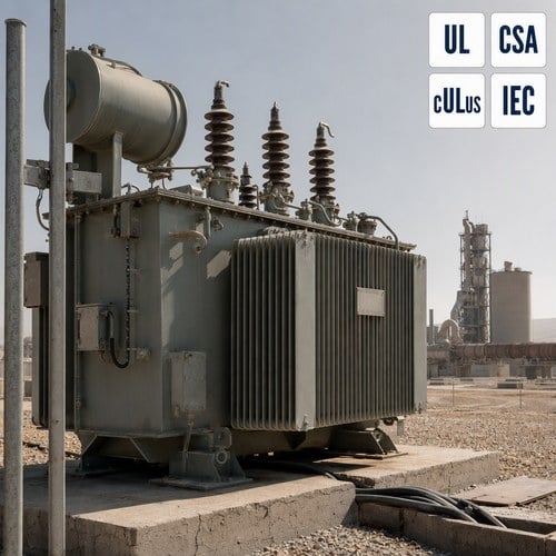
What a Cement Plant Load Profile Does to a Standard Specification
A modern cement plant consumes roughly 110 to 120 kWh of electrical energy per tonne of cement, and electric motors account for the large majority of that figure — industry assessments put motor load at 65 to 75 percent of plant electricity use. The heavy end of that load sits in comminution: the raw mill, the cement mill and, on more recent lines, a roller press, each driven by a main motor in the 3 to 6 MW class.
The demand side agrees. The U.S. Department of Energy study of cement plant electricity use identifies the large grinding mills as the biggest single electrical loads on site, and notes that these plants typically run continuously for months between shutdowns. Both of those numbers matter to the specification: a plant with no daily load cycle carries a load factor of 0.8 to 0.9 of nameplate for long stretches, which is a different thermal proposition from an industrial plant that peaks twice a day. Sector-level context is tracked on the IEA cement sector page, and the underlying plant data comes from the LBNL/DOE cement industry study.
Three specification quantities get under-specified on cement projects more often than any others: motor starting kVA, harmonic content from mill drives, and the site’s real ambient and dust conditions. The rest of this guide works through each of them in the order they usually cause trouble.
Sizing Around Mill Motor Starts, Not Around Running kW
The usual RFQ arrives with connected load in kW and a request for "a transformer to suit". That is not enough information to size a cement plant transformer. Starting kVA is what sets the voltage dip, and starting kVA is driven by locked-rotor current, not by running power.
Take a 4 MW, 6.6 kV raw mill motor with a locked-rotor current of six times full-load current, 0.94 efficiency and 0.90 power factor. Rated motor kVA is about 4.7 MVA, so starting kVA lands near 28 MVA — roughly six times the motor’s rated apparent power. The bus dip that follows can be approximated as (starting kVA × transformer impedance %) ÷ transformer rating. Ignoring the supply impedance, which is only valid on a stiff utility feed, the arithmetic looks like this:
| Transformer rating | Impedance | Approx. bus dip on a 28 MVA mill start | Practical reading |
|---|---|---|---|
| 6 MVA | 7.5% | 35% | Mill starter will not hold in; motor protection trips |
| 10 MVA | 7.5% | 21% | Marginal — needs reduced-voltage or soft start |
| 16 MVA | 8.0% | 14% | Workable on a firm source; check the upstream fault level |
| 20 MVA | 8.0% | 11% | Comfortable starting, but confirm short-circuit withstand |
Transformer sizing on a cement site therefore starts from the motor list rather than from the connected load total. Those figures assume the mill is the only large motor starting, and that the source is strong enough to be ignored. In practice, a weak utility feed caps the dip no matter how large the transformer is, and the answer becomes a soft starter, a VFD, or a motor starting study rather than a bigger oil immersed transformer. Motor starting voltage dip, locked-rotor current and impedance are worked through in more detail in our motor starting guide.
Harmonics: Why the Drive-Friendly Spec Usually Stops Halfway
Most cement lines built or upgraded in the last decade run their mills and fans through variable frequency drives, and a six-pulse drive draws a current waveform rich in fifth and seventh harmonics before any filtering. Those currents do two things: they distort the plant bus, and they generate extra eddy-current losses inside the transformer windings, which appear as local hot spots rather than as a rise the oil thermometer will show you. The consequence for a cement plant transformer is that the winding hot spot, not the top-oil temperature, becomes the limiting condition.
IEEE 519 sets the harmonic current limits measured at the point of common coupling, and for the short-circuit ratios normally found on a plant bus the total demand distortion limit lands in the single digits — which is why measured compliance, not a claimed K-rating, is what a utility interconnection review will ask for. variable frequency drive harmonics are therefore a specification input, not a downstream problem.
K-factor transformers exist for exactly this loading, and they are the standard answer where variable frequency drive harmonics are present in quantity. The K-factor number is the sum, across harmonic orders, of the squared per-unit harmonic current multiplied by the square of its order: a 25 percent fifth harmonic contributes 0.25² × 5² = 6.25 per unit of eddy loss on its own. K-4, K-9 and K-13 units are built so the winding and core losses stay inside the design gradient under that spectrum, and the marking is defined in the UL dry-type transformer standard.
For large oil immersed transformer units, a K-rating alone is not the whole answer. The thermal question is handled by derating the unit for the actual harmonic spectrum, which is what IEEE C57.110 describes, and by asking the supplier to show harmonic loss calculations rather than a nameplate suffix. Where the spectrum is severe, the cheaper engineering is often upstream: a twelve-pulse configuration, an active front end, or a detuned filter bank on the drive bus.
Dust, Heat and Cooling: The Site Conditions That Decide the Enclosure
Transformer temperature rise is specified against a maximum ambient of 40°C in the usual IEC 60076 basis. Cement plants in the Gulf, the Sahel and parts of South Asia routinely sit at 45 to 50°C shade temperature, with radiant heat from kiln shells and preheater towers adding to the local load. Above the reference ambient the unit must be derated, or ordered with a lower design gradient — the same rating will simply run hotter and age faster.
Dust is the second half of the problem, and it is a cooling problem before it is a cleanliness problem. Cement and raw-meal dust is fine, alkaline and mildly conductive once it takes up moisture, so it bridges creepage paths around bushings and terminal boxes. It also packs the gaps in corrugated tank walls and radiator fins, which is where a large oil immersed transformer sheds most of its heat. A forced-cooled unit with clogged filters loses the forced rating entirely and falls back to its self-cooled rating at the exact moment the plant is running hardest.
What that translates into at the specification stage: wider fin or radiator spacing where the site is dust-heavy, IP54 or better termination enclosures, seals and gaskets rated for alkaline dust, and a maintained differential-pressure indication on any forced-cooled bank so the maintenance team can see filter loading before it costs capacity. Where a dry-type unit is used indoors in an MCC room, enclosure selection follows the same logic — filter, seal, and plan the cleaning interval. Transformers specified for hot and dusty sites follow a comparable set of rules.
Certification and Test Evidence to Demand at the FAT
For North American cement projects the certification question is settled before the performance question, because the inspector arrives with a list. Liquid-filled and dry-type units must carry the listing appropriate to their category, Canadian sites need CSA marks or a recognized equivalent, and IEC markets are covered by IEC 60076, with IEC 60076-11 applying to dry-type units. General requirements and test methods for liquid-immersed units are set out in IEEE C57.12.00 and IEEE C57.12.90.
Beyond the mark, the factory acceptance test is where a cement project earns or loses its commissioning schedule. Ratio, polarity, winding resistance, no-load loss, load loss, impedance, applied and induced potential, plus temperature rise and impulse as type tests, are the baseline. Two additions are worth the extra day in the test bay: a measured temperature-rise report tied to the site ambient rather than a generic 40°C statement, and a sweep frequency response analysis fingerprint taken before shipment so that any transport damage can be detected by comparison at site rather than argued about.
How We Build and Test Units for Cement Duty
Ryan Electric has manufactured distribution and power transformers since 2007 from a 120,000 m² production base with more than 180 sets of production and test equipment and 37 patents, and has held a joint venture partnership with Eaton since 2023. Cement duty units come off the same lines as our utility and data centre work, in both oil immersed transformer and dry-type construction.
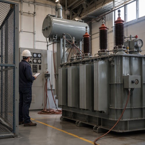
On cement projects we measure no-load and load loss on every unit instead of quoting design values, and we treat harmonic loss headroom as a per-project calculation driven by the customer’s drive schedule. The first document our application engineers ask for is not the transformer specification but the drive list — how many drives, what pulse number, and whether a roller press is in the circuit — because that sheet settles K-factor, impedance class and cooling, in that order.
The other habit that saves commissioning weeks is packaging. A cement plant is usually inland, which means road or rail beyond the port, so units are braced for overland shock, oil is shipped in sealed drums on larger ratings, and the SFRA fingerprint travels with the test report so the site team has a baseline to compare against.
Ordering Around the Kiln Shutdown Window
A cement plant does not stop for a transformer. It stops for a shutdown, and the shutdown date is fixed by the kiln campaign, which is why the procurement clock has to run backwards from that date rather than forwards from the order. transformer sizing and lead-time planning both belong on that clock.
Send us the one-line diagram, the drive list, the site ambient and the shutdown date, and we will come back with a rating, an impedance class, a cooling arrangement and a date. Contact our application engineering team at [email protected] or +86-15371760308 and we will run the starting and harmonic figures against your actual motor list.
About the Author: This guide was prepared by the application engineering team at Jiangsu Ryan Electric Co., Ltd. (Ryan Transformers), which has designed and manufactured oil immersed and dry type transformers for industrial, utility and data centre customers since 2007. Project-specific questions on mill starting, harmonic derating or site ambient derating are answered directly by the engineering team at [email protected].
Table of Contents
- What a Cement Plant Load Profile Does to a Standard Specification
- Sizing Around Mill Motor Starts, Not Around Running kW
- Harmonics: Why the Drive-Friendly Spec Usually Stops Halfway
- Dust, Heat and Cooling: The Site Conditions That Decide the Enclosure
- Certification and Test Evidence to Demand at the FAT
- How We Build and Test Units for Cement Duty
- Ordering Around the Kiln Shutdown Window